
MB32S LEIDITECH
Document overview
- Manufacturer or author: Provided By www.digicamel.com(FREE DATASHEET DOWNLOAD SITE)
- PDF pages: 3
Technical content
Features
Low power loss,high efficiency Ideally suited for automatic assembly High temperature soldering 260℃/10 seconds at terminals Component in accordance to RoHS 2011/65/EU Mechanical Date Case: MBS Molding compound meets UL 94 V-0 flammability rating Terminals: Solder plated, solderable per MIL-STD-750, Method 2026 Polarity:As marked on case Marking: type number Maximum Ratings & Thermal Characteristics A =25℃ unless otherwise noted)
Electrical Characteristics
A =25℃ unless otherwise noted) MB 325S MB315S~ MB320S MB38S~ MB310S MB35S~ MB36S MB32S~ MB345S Items Forward voltage per element at I F =3.0A Peak reverse current at rated DC blocking voltage 0.1 0.05 5.010 30 40 45 21 28 30 40 3.0 -55 to +150 MB 34S MB 33S MB 32S SymbolItems Maximum repetitive peak reverse voltage Maximum RMS voltage Maximum DC blocking voltage Maximum average forward rectified current at T L =65℃ V RRM V RMS V DC I F(AV) T A =25℃ T A =100 V F I R UnitSymbol Peak forward surge current 8.3 ms single half sine-wave superimposed on rated load Thermal resistance from junction to lead (1) Operating junction and storage temperature range I FSM R θJL T J STG 50 60 80 100 150 200 250 50 60 80 100 150 200 250 2502001057056423531 Unit MB 325S MB 320S MB 315S MB 310S MB 38S MB 36S MB 35S MB 345S V V Note 1: Mounted on aluminum substrate PC board with 1.3mm solder V mA A A ℃/W V Major Ratings and Characteristics 3.0A V RRM
20 V to 250 V
I FSM 80A V F T J max. 150°C I F(AV) MB32S~MB325S Schottky Mount glass Passivatd Bridge Rectifier Rev 2.0 : www.leiditech.com 12.01.2019 1/3
A =25℃ unless otherwise noted) 0.5 1.5 2.5 3.5 0 30 60 90 120 150 Lead Temperature(°C) Average Forward Current (A) Fig.1 Foward Current Derating Curve 100 1 10 100 Peak Forward Surge Current (A) Fig.2 Maximum Non-Repetitive Peak Forward Surge Current Number of Cycles at 60Hz 0.01 0.1 100 Instantaneous Forward Voltage (V) Fig.3 Typical Forward Current Characteristics Instantaneous Forward Current (A) 0.01 0.1 100 0 20 40 60 80 100 Fig.4 Typical Reverse Characteristics Instantaneous Reverse Leakage(mA) T J = 100°C Percent of Rated Peak Reverse Voltage (%) MB32S~MB345S MB35S~MB36S MB38S~MB310S MB315S~MB320S MB325S T J = 25°C MB32S~MB325S Rev 2.0 : www.leiditech.com 12.01.2019 2/3
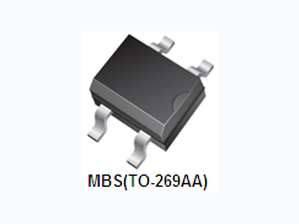
0.031 (0.8) 0.019 (0.5) 0.014 (0.35) 0.006 (0.15) 0.008 (0.20) 0.004 (0.10) 0.161 (4.1) 0.142 (3.6) 0.252 (6.4) 0.275 (7.0) 0.106 (2.70) 0.090 (2.30) 0.108 (2.74) 0.090 (2.30) 0.195 (4.95) 0.177 (4.50) 0.043 (1.1) 0.020 (0.5) 0.272 MAX. (6.91 MAX.) 0.030 MIN. (0.76 MIN.) 0.023 MIN. (0.58 MIN.) 0.105 (2.67) 0.095 (2.41) TO-269AA (MBS) Mounting Pad Layout Dimensions in millimeters and (inches) MB32S~MB325S Shanghai Leiditech Electronic Co.,Ltd Email: sale1@leiditech.com Tel : +86- 021 50828806 Fax : +86- 021 50477059 Rev 2.0 : www.leiditech.com 12.01.2019 3/3