
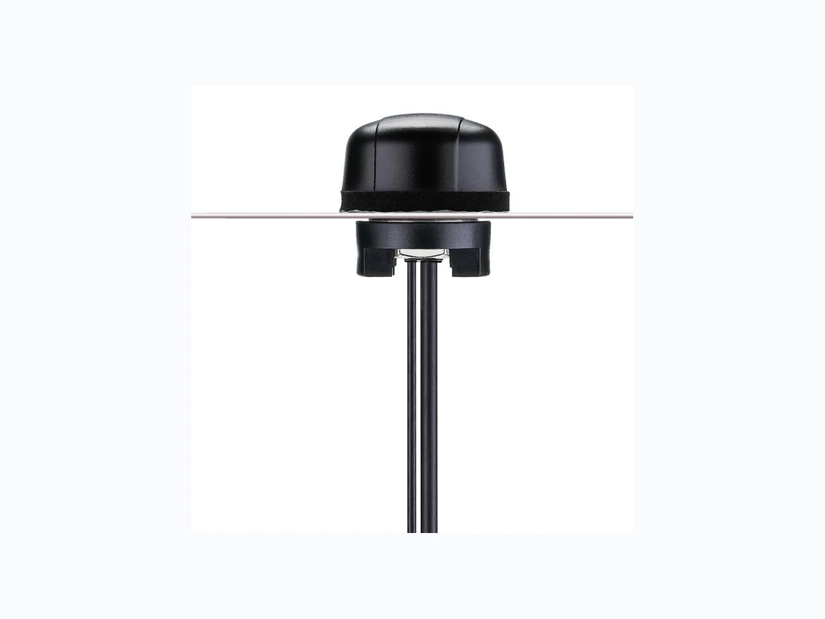
MA501CAC001 ETC2
Document overview
- Manufacturer or author: Provided By www.digicamel.com(FREE DATASHEET DOWNLOAD SITE)
- PDF pages: 13
Technical content
SPE-11-8-079/C Page 1 of 13 MA.501.C.A301111.C305151 SPECIFICATION Model No. : MA501.C.AC.001 Product Name : Heavy Duty Screw Mount Antenna – GPS/Dual- Band 2.45.2GHz Description : 2.4GHz5.2GHz suitable for ISM Bands/ZigBee/WLAN/Bluetooth IEEE.802.11/IEEE.802.15 UV and vandal resistant ABS housing IP67 & IP69K Waterproof Compliance Height 29mm Diameter 49mm RoHS Compliant
SPE-11-8-079/C Page 2 of 13 MA.501.C.A301111.C305151 1. Introduction MA.501 is a combination of high performance GPS and dual band Wi -Fi (2.42.5/5.2GHz) antenna solution for reliable location informat ion with localised data transfer via WLAN, Zigbee or Wi -Fi. This product incorporates the industry’s most advanced GPS active ceramic patch technology (XtremeGain™) allowing for gains of up to 300% in accuracy compared to traditional antennas. Time to first fix is under 1 minute with all of the industry leading GPS receivers. XtremeGain technology means the antenna has been tuned for the Hercules environment giving you the optimum antenna solution to enable elimination of data gaps. The 2.4/5.2GHz antenna inside has also been tuned for this enclosure; hence performance is excellent at all bands meaning the antenna works worldwide. It was designed mainly for commercial vehicle and outdoor equipment installations, with extra thick threads, with the cables exiting through the bottom for ease of install. Durable and robust UV resistant PVC housing is resistant to vandalism and direct attack. It is designed for covert mounting as it is only 3cm high when mounted, thus complies with the latest EU directives for height restrictions. The antenna housing is completely waterproof to IP67, and also to IP69K, which means it is waterproof against high pressure water jets used in industrial environments for cleaning. 2. Features GPS High LNA Gain up to 32 dB ± 2 dB Miniaturized – diameter 49mm Low Noise (1.5 dB max) Resides in its own chamber and is tuned for the Hercules environment to enhance performance WLAN / Wi-Fi Advanced dual-band antenna for worldwide application Tuned for the Hercules environment to enhance performance
SPE-11-8-079/C Page 3 of 13 MA.501.C.A301111.C305151 Other Weatherproof (IP67 & IP69K) with robust foam seal Quality textured covert and low profile design UV and Vandal resistant PVC housing 3. Specifications GPS Frequency 1575.42MHz Average Gain 32dB typ. Gain @ Zenith 2.0dBi min. Gain @ 10 o Elevation -4.0dBi min. Axial Ratio 3.0dB max. Polarization Right Hand Circular VSWR <=2.0:1 Impedance 50Ω Noise Figure 1.5dB max. Bandwidth 10Mhz min. LNA Out-band Attenuation fo = 1575.42MHz fo ± 30 MHz 5dB Min. fo ± 50 MHz 20dB Min. fo ± 100 MHz 25dB Min. Input Voltage Min:1.8V Typ. 3.0V Max: 5.5V Total Gain @ Zenith 25dBic 30dBic 32dBic Current Consumption 6mA 12mA 30mA Noise Figure 2.7dB 3.0dB 3.7dB Cable 3m RG174 standard, fully customizable Connector SMA(M) standard, standard, fully customizable WiFi 47.5 VSWR <=1.8:1 Impedance 50Ω Polarization Linear - Horizontal
SPE-11-8-079/C Page 4 of 13 MA.501.C.A301111.C305151 Radiation Pattern Omni Cable 3m CFD-200 standard, fully customizable Connector RP-SMA(M) standard, standard, fully customizable MECHANICAL Dimensions Height 29mm x Diameter 49mm Casing UV resistant PVC Base and thread Nickel plated Zinc Alloy Thread diameter 18mm Weather proof gasket CR4305 foam with 3M9448B double-side adhesive Cable pull 8 Kgf Recommended Mounting Torque 95Nm Maximum Mounting Torque 135Nm ENVIRONMENTAL Waterproof IP67 & IP69K Corrosion 5% NaCl for 96hrs - Nickel plated zinc alloy base and thread Temperature Range -40°C to +85°C Thermal Shock 100 cycles -40°C to +80°C Humidity Non-condensing 65°C 95% RH Shock (drop test) 1m drop on concrete 6 axes
SPE-11-8-079/C Page 5 of 13 MA.501.C.A301111.C305151 4. S11 Return Loss management (Wi-Fi / WLAN) Y X Z Note : 1. The upper of the PCB is X direction. 2. Connector is toward Z direction.
SPE-11-8-079/C Page 6 of 13 MA.501.C.A301111.C305151 5. VSWR (Wi-Fi / WLAN) 6. System Block Diagram
SPE-11-8-079/C Page 7 of 13 MA.501.C.A301111.C305151 7. GPS Patch Radiation Pattern
SPE-11-8-079/C Page 8 of 13 MA.501.C.A301111.C305151 8. LNA Properties 8.1. LNA Gain and Out-band Rejection @ 3.0V
SPE-11-8-079/C Page 9 of 13 MA.501.C.A301111.C305151 8.2. Noise Figure
SPE-11-8-079/C Page 10 of 13 MA.501.C.A301111.C305151 9. Drawings
SPE-11-8-079/C Page 11 of 13 MA.501.C.A301111.C305151
SPE-11-8-079/C Page 12 of 13 MA.501.C.A301111.C305151 10.Packaging
SPE-11-8-079/C Page 13 of 13 MA.501.C.A301111.C305151 11. Installation Recommended torque for mounting is 95Nm or 70ftlbs Maximum torque for mounting is 135.6Nm or 100ft lbs