
MA231LBC003 TAOGLAS
Document overview
- Manufacturer or author: Provided By www.digicamel.com(FREE DATASHEET DOWNLOAD SITE)
- PDF pages: 24
Technical content
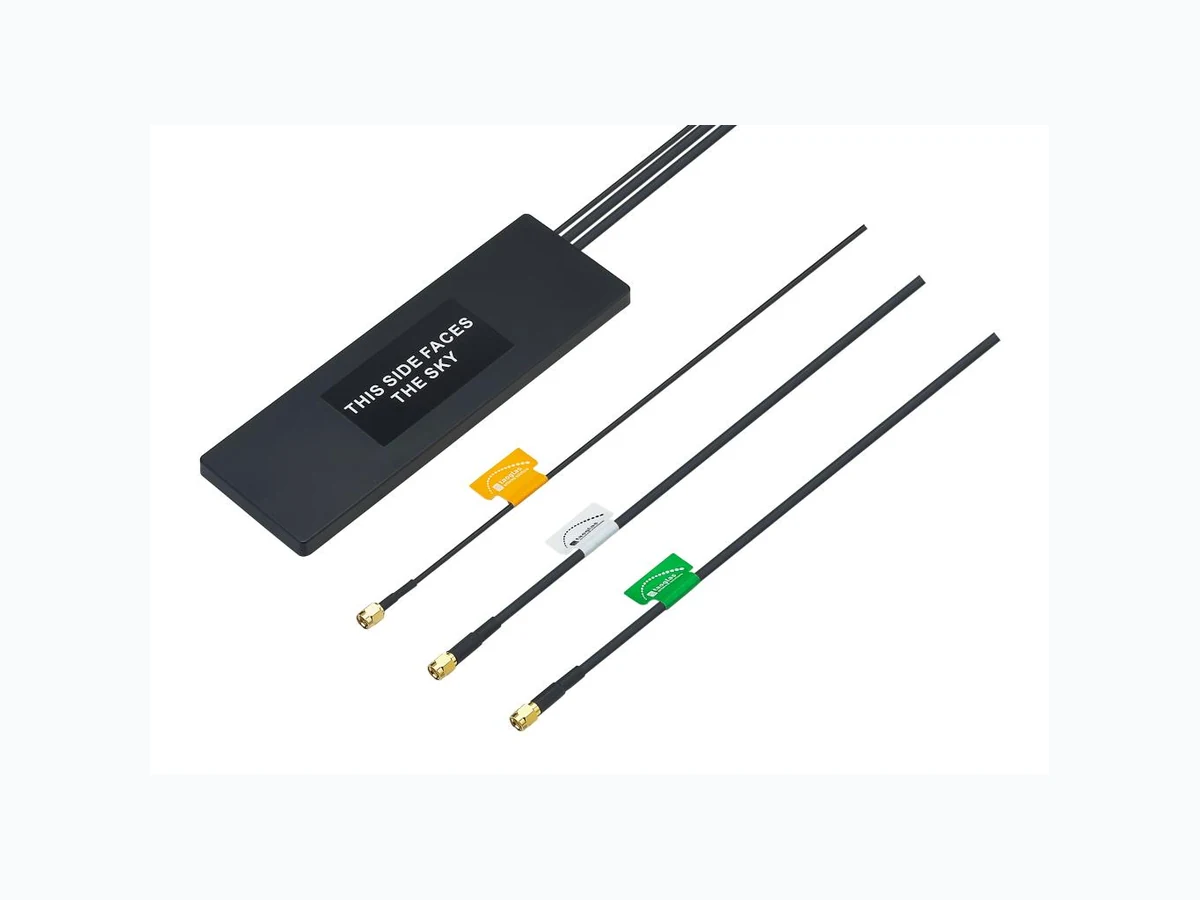
SPE-17-8-010/A Page 1 of 24 SPECIFICATION Part No. : MA231.LBC.003 Product Name : MA231 3 in1Stream 3M: GPS -GLONASS-GALILEO RG174 RP-SMA(M), 2G/3G/4G CFD -200 RP-SMA(M), Wi-Fi CFD-200 RP-SMA(M) Feature : IP67 Antenna GPS-GLONASS-GALILEO: 3M RG-174 SMA(M) ST 1.8~5.5V/30dB Cellular 4G/3G/2G: 3M Low Loss CFD-200 SMA(M) ST Wi-Fi: 3M Low Loss CFD-200 RP-SMA(M) ST Dimensions: 200.5*66.5*9mm RoHS Compliant
SPE-17-8-010/A Page 2 of 24 1. Introduction The Stream 3in1 MA23 1 GPS-GLONASS-GALILEO, LTE Cellular 4G/3G/2G and Wi-Fi 2.4/5.8GHz antenna is a low profile, heavy-duty, fully IP67 waterproof external M2M antenna for use by RF professionals in telematics, transportation and remote monitoring applications. The Stream 3in1 is unique in the market as it combines the highest possible efficiency and peak gain for GPS-GLONASS-GALILEO, Wi-Fi dual-band 2.4/5.8GHz and all cellular bands in 4G/3G/2 G in a low profile compact format for mounting via high quality first tier automotive approved 3M adhesive foam. The pat ent pending design incorporates a custom Taoglas 35mm GPS-GLONASS-GALILEO patch antenna on an extended integral ground -plane. A front-end SAW filter dramatically reduces radiated spurious emissions. The extended ground-plane used with an innovative internal 4G/3G/2G Cellular PIFA also enables the unique wide -band 4G/3G/2G response to deliver the highest performance possible, at 3 meters cable length. High antenna efficiencies are absolutely critical in today’s 4G and 2G systems to achieving targeted data-speeds and coverage. A powerful Wi-Fi dual-band 2.4/5.8GHz antenna gives maximum gain and coverage for common applications. The Stream works best when attached to plastic or glass, but can also be used on metal if a minimum of 40mm foam spacing is added.
SPE-17-8-010/A Page 3 of 24 2. Specification Table Performance Specifications Parameter GPS-GLONASS- GALILEO Antenna Cellular Antenna Wi-Fi Antenna Frequency Range 1,575.42±10MHz 1,602±8MHz 700-960MHz 1710-2170MHz 2500-2690MHz 2400-2484MHz 5150-5850MHz Gain 1575.42MHz:1.3dBi typ. @ Zenith 1602MHz:2.9dBi typ. @ Zenith Listed below Listed below VSWR 2.0 Max 3.0 Max 2.0 Max Impedance 50Ω 50Ω 50Ω Efficiency - ≧ 70% @ 700MHz ≧ 60% @ 750MHz ≧ 50% @ 824MHz ≧ 50% @ 880MHz ≧ 40% @ 890MHz ≧ 25% @ 960MHz ≧ 50% @ 1710MHz ≧ 50% @ 1880MHz ≧ 50% @ 1990MHz ≧ 45% @ 2110MHz ≧ 45% @ 2170MHz ≧ 30% @ 2500MHz ≧ 15% @ 2690MHz ≧ 35% @ 2450MHz ≧ 35% @ 5250MHz ≧ 35% @ 5650MHz
SPE-17-8-010/A Page 4 of 24 MECHANICAL Cable / Connector 3M RG-174 with SMA(M) Fully customizable 3M CFD-200 with SMA(M) Fully customizable 3M CFD-200 with RP-SMA(M) Fully customizable Housing ABS Adhesive Mount 3M 1600TB(196.57*62.57*1.25mm) Protection Class IP-67 Weight 180g ENVIRONMENTAL Operation Temperature -40°C to +85°C Storage Temperature -40°C to +85°C Relative Humidity 20% to 95%
SPE-17-8-010/A Page 5 of 24 3. GPS-GLONASS-GALILEO Antenna Return Loss Return Loss: -18.70 dB@1575.42MHz Return Loss: -13.21 dB@1602MHz
SPE-17-8-010/A Page 6 of 24 Smith Chart Impedance: 46.61+j10.76 Ohm@1575.42MHz Impedance: 63.18-j21.73 Ohm@1602MHz
SPE-17-8-010/A Page 7 of 24 Radiation Patterns
SPE-17-8-010/A Page 8 of 24 3.3.1. XZ Plane 1575.42MHz 1575.42MHZ Peak Gain Zenith Gain V+H 1.39 dBi 1.35 dBi 3.3.2. XZ Plane 1602MHz 1602MHZ Peak Gain Zenith Gain V+H 3.19 dBi 3.19 dBi
SPE-17-8-010/A Page 9 of 24 3.3.3. YZ Plane 1575.42MHz 1575.42MHZ Peak Gain Zenith Gain V+H 1.92 dBi 1.92 dBi 3.3.4. YZ Plane 1602MHz 1602MHZ Peak Gain Zenith Gain V+H 2.92 dBi 2.92 dBi
SPE-17-8-010/A Page 10 of 24 Axial Ratio Pattern 3.4.1. 1575.42MHz 3.4.2. 1602MHz
SPE-17-8-010/A Page 11 of 24 LNA characteristics Parameter Frequency Range 1,575.42±10MHz For GPS/GALILEO 1,602±8MHz For GLONASS Output Impedance 50 Ohm Output VSWR 2.0 max Supply Voltage Gain(Typ) Noise Figure(Typ) Power Consumption(Typ) 1.8V 24dB - 5.5mA 3.0V 30dB 2.4dB For GPS/GALILEO 2.7dB For GLONASS 13.2mA 5.5V 32dB - 16.2mA
SPE-17-8-010/A Page 12 of 24 LNA Noise Figure@3.0V for 1575.42MHz LNA Noise Figure@3.0V for 1602MHz
SPE-17-8-010/A Page 13 of 24 LNA Gain and Output of VSWR at 3.0V
SPE-17-8-010/A Page 14 of 24 4. Cellular 4G/3G/2G antenna VSWR Efficiency
SPE-17-8-010/A Page 15 of 24 Peak Gain Average Gain
SPE-17-8-010/A Page 16 of 24 Antenna Radiation Pattern X Z Y
SPE-17-8-010/A Page 17 of 24 XY Plane X Y X Y X Y
SPE-17-8-010/A Page 18 of 24 ZX Plane Z X Z X Z X
SPE-17-8-010/A Page 19 of 24 ZY Plane Z Y Z Y Z Y
SPE-17-8-010/A Page 20 of 24 5. Wi-Fi 2.4/5.0 GHz antenna VSWR Efficiency
SPE-17-8-010/A Page 21 of 24 Peak Gain Average Gain
SPE-17-8-010/A Page 22 of 24 2D Radiation Pattern XY Plane XZ Plane YZ Plane Z Y Z Y Z X Z X X Y X Y
SPE-17-8-010/A Page 23 of 24 6. Mechanical Drawing
SPE-17-8-010/A Page 24 of 24 7. Packaging Taoglas makes no warranties based on the accuracy or completeness of the contents of this document and reserves the right to make changes to specifications and product descriptions at any time without notice. Taoglas reserves all rights to this document and the information contained herein. Reproduction, use or disclosure to third parties without express permission is strictly prohibited. Copyright © Taoglas Ltd.