
MA230LBC002 ETC2
Document overview
- Manufacturer or author: Provided By www.digicamel.com(FREE DATASHEET DOWNLOAD SITE)
- PDF pages: 29
Technical content
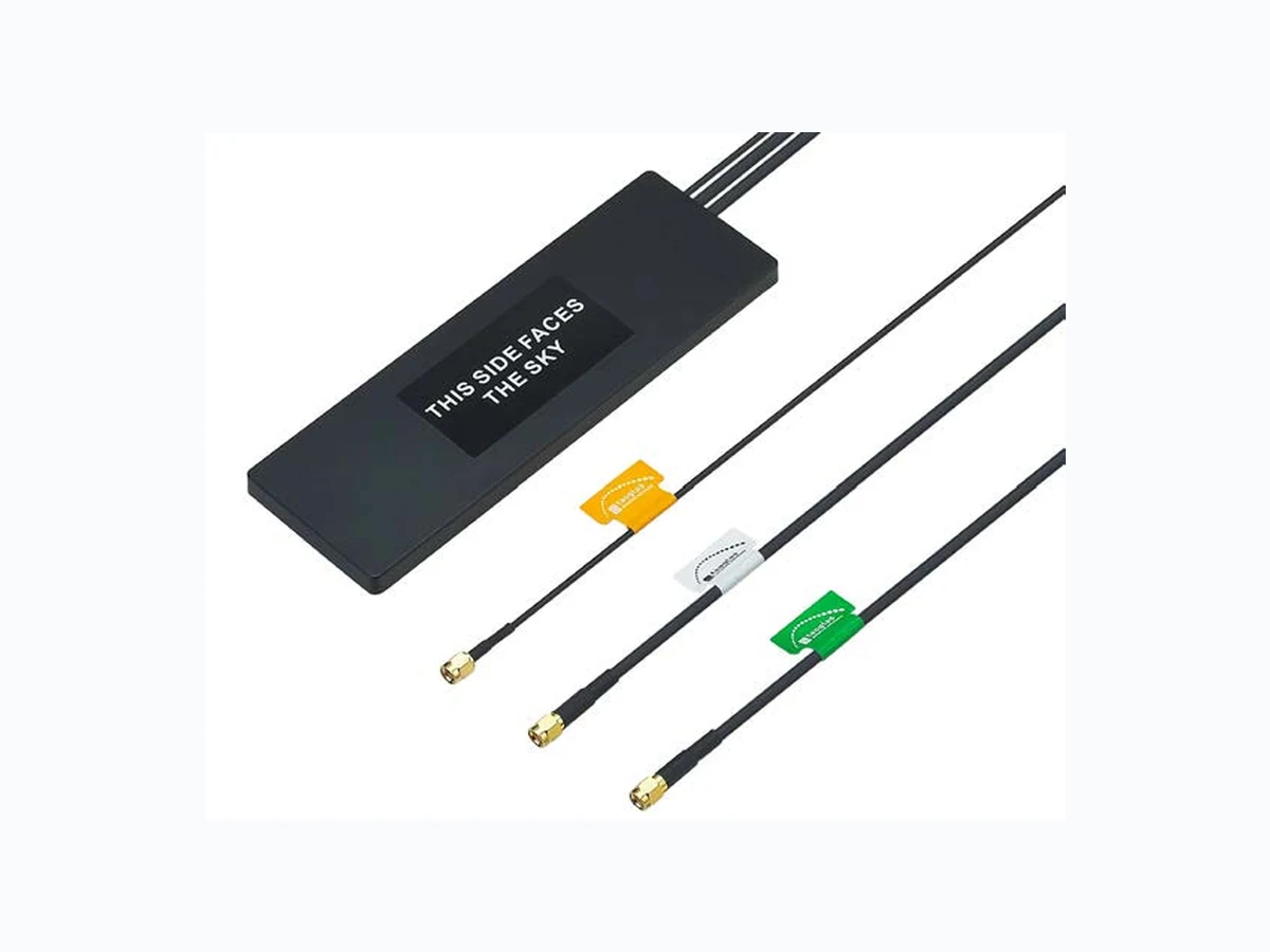
SPE-13-8-068/B/PK | page 1 of 29 MA230.A301111.B305111.C305151 MA230.LBC.002 Specification Part No. MA230.LBC.002 Product Name Stream MA.230 Stream 3 in 1 High Performance Adhesive Mount Combination Antenna GNSS - GPS/Glonass Cellular - LTE/HSPA/GSM/CDMA/UMTS Wi-Fi - 2.4/5 GHz Feature IP67 Antenna GPS/Glonass: 3M RG-174 SMA(M) 1.8~5.5V/30dB Cellular 2G/3G/4G: 3M Low Loss CFD-200 SMA(M) Wi-Fi: 3M Low Loss CFD-200 RP-SMA(M) Dimensions: 200.5*66.5*9mm RoHS Compliant Topside View Underside View Stream
SPE-13-8-068/B/PK | page 2 of 29 MA230.A301111.B305111.C305151 The Stream 3in1 MA.230 GPS/Glonass, LTE Cellular 2G/3G/4G and Wi-Fi 2.4/5GHz antenna is a low profile, heavy-duty, fully IP67 waterproof external M2M antenna for use by RF professionals in telematics, transportation and remote monitoring applications. The Stream 3in1 is unique in the market as it combines the highest possible efficiency and peak gain for GPS/Glonass, Wi-Fi dual-band 2.4/5GHz and all cellular bands in 2G/3G/4G in a low profile compact format for mounting via high quality first tier automotive approved 3M adhesive foam. GPS/Glonass The patent pending design incorporates internally a custom Taoglas 35mm patch antenna on an extended integral ground-plane to deliver more than 3.5dBiC gain. A front-end SAW filter dramatically reduces radiated spurious emissions. Cellular 2G/3G/4G The extended ground-plane used with an innovative internal cellular PIFA also enables the unique wide-band 2G/3G/4G response to deliver the highest performance possible, at 3 metres cable length. Nothing else out there comes close in terms of consistency of efficiency and peak gain at all cellular bands, with 70%+ at the LTE 700MHz band, again including 3 metres of cable loss. High antenna efficiencies are absolutely critical in today’s 3G and 4G systems to achieving targeted data-speeds and coverage. Wi-Fi dual-band 2.4/5GHz A powerful antenna gives maximum gain and coverage for common applications. 3dBi+ stable gain on both bands including cable loss means the antenna is ideal for high bandwidth applications. All this is done while still maintaining 20dB isolation between antennas. The Stream uses shielded PTFE dielectric ultra low-loss cables that maintain low attenuation at all frequency bands, and high noise rejection, with an average loss of only 0.3dB per meter (0.1dB per foot), compared to 0.7dB for RG58 and 1.2dB for RG174. Because of this, the Stream maximizes chances of passing PTCRB and network approvals first time. The Stream works best when attached to plastic or glass, but can also be used on metal if a minimum of 40mm foam spacing is added. 1. Introduction
SPE-13-8-068/B/PK | page 3 of 29 MA230.A301111.B305111.C305151 2. Specification Parameter GPS/Glonass Antenna Cellular Antenna Wi-Fi Antenna Features High performance LTE: 700MHz High performance GPS/Glonass 35*35*4mm CDMA: 824~896MHz dual-band Wi-Fi 2.4/5 GHz ceramic patch antenna GSM: 880~960MHz DCS: 1710-1880 MHz PCS: 1850~1990MHz 3G: 1920~2170MHz 1602MHz 3.19dBi typ @ Zenith -4.34dBi at 1710~2170MHz 2.0dBi typ. @ 5000MHz Peak:2.16dBi at 700~960MHz 0.42dBi at 1710~2170MHz VSWR 1.21 Max at 1575MHz 3.3 Max. at 700~960MHz 2.30 Max at 2400MHz 1.55 Max at 1602MHz 3.6 Max. at 1710~1850MHz 1.08 Max at 5000MHz 2.2 Max. at 1880~2170MHz Impedance 50Ω 50Ω 50Ω Efficiency ≥ 68% @ 700MHz ≥ 40% @ 2450MHz ≥ 72% @ 750MHz ≥ 30% @ 5000MHz ≥ 66% @ 824MHz ≥ 56% @ 890MHz ≥ 61% @ 880MHz ≥ 53% @ 960MHz ≥ 37% @1710MHz ≥ 51% @1880MHz ≥ 55% @1990MHz ≥ 54% @2110MHz ≥ 45% @2170MHz
SPE-13-8-068/B/PK | page 4 of 29 MA230.A301111.B305111.C305151 2. Specification Mechanical Cable / Connector 3M RG-174 with SMA(M) 3M CFD-200 with SMA(M) 3M CFD-200 with RP-SMA(M) Fully Customisable Fully customisable Fully customisable Housing UV resistant ABS Adhesive Mount 3M 1600TB (196.57*62.57*1.25mm) Protection Class IP-67 Weight per unit 0.18kg Environmental Operation Temperature -40°C to +85°C Storage Temperature -40°C to +85°C Relative Humidity 20% to 95%
SPE-13-8-068/B/PK | page 5 of 29 MA230.A301111.B305111.C305151 3. GPS-GLONASS antenna
3.1 Return Loss
1:-18.707 dB
1.57542 GHz
2:-9.7277 dB
1.59200 GHz
3:-13.219 dB
1.60200 GHz
CENTER 1.592.000 000 MHz SPAN 200.000 000 MHz Return Loss: -18.70 dB @ 1575MHz Return Loss: -13.21 dB @ 1602MHz CH1 RFL /M LOG 5 dB / REF .5 dB 4: - 9.7277 dB 1 592. 000 000 MHz 1. 592 GHz
SPE-13-8-068/B/PK | page 6 of 29 MA230.A301111.B305111.C305151 3. GPS-GLONASS antenna
3.2 Smith Chart
1: 46.615 Ω 10.760 Ω 2: 98.805 Ω 0.3359 Ω 3: 63.187 Ω -21.713 Ω CENTER 1 592. 000 000 MHz SPAN 200.000 000 MHz 1. 592 GHz Impedance: 46.61 + j10.76 Ohm@ 1575MHz Impedance: 63.18 - j21.73 Ohm@ 1602MHz CH1 RFL /M 1 U FS 4: 98. 805 Ω 0.3359 Ω 33. 584 pH 1 592. 000 000 MHz
SPE-13-8-068/B/PK | page 7 of 29 MA230.A301111.B305111.C305151 3. GPS-GLONASS antenna
3.3 VSWR
3.4 Radiation Patterns
CH1 RFL /M SWR 1 / REF 1 4: 1.9017 1 592. 000 000 MHz 1. 592 GHz CH1 Markers 1: 1.2104 2: 1.9017 3: 1.5505 CENTER 1 592. 000 000 MHz SPAN 200.000 000 MHz VSWR: 1.21 @ 1575MHz VSWR: 1.55 @ 1602MHz XZ - Plane YZ - Plane
-10 -15 -20 -25 -30 -35 -40 -45 SPE-13-8-068/B/PK | page 8 of 29 MA230.A301111.B305111.C305151 3.4.1 XZ Plane 1575.42MHz Horizontal & Vertical Pattern Model No. Test Mode Freq (MHz) Max Gain(dBi) Min Gain(dBi) Avg. Gain(dBi) Source Polar.
1575 MHz Peak Gain Zenith Gain
V+H 1.39 1.35 dBi
SPE-13-8-068/B/PK | page 9 of 29 MA230.A301111.B305111.C305151 90 270 180 -10 -15 -20 -25 -30 -35 -40 -45
3.4.2 XZ Plane 1602MHz Horizontal & Vertical
Pattern Model No. Test Mode Freq (MHz) Max Gain(dBi) Min Gain(dBi) Avg. Gain(dBi) Source Polar.
1602 MHz Peak Gain Zenith Gain
V+H 3.19 3.19 dBi
SPE-13-8-068/B/PK | page 10 of 29 MA230.A301111.B305111.C305151 90 270 180 -10 -15 -20 -25 -30 -35 -40 -45 3.4.3 YZ Plane 1575.42MHz Horizontal & Vertical Pattern Model No. Test Mode Freq (MHz) Max Gain(dBi) Min Gain(dBi) Avg. Gain(dBi) Source Polar. V+H 1.92 1.92 dBi
SPE-13-8-068/B/PK | page 11 of 29 MA230.A301111.B305111.C305151 90 270 180 -10 -15 -20 -25 -30 -35 -40 -45
3.4.4 YZ Plane 1602MHz Horizontal & Vertical
Pattern Model No. Test Mode Freq (MHz) Max Gain(dBi) Min Gain(dBi) Avg. Gain(dBi) Source Polar. V+H 2.92 2.92 dBi
SPE-13-8-068/B/PK | page 12 of 29 MA230.A301111.B305111.C305151
3.5 LNA characteristics
3.6 LNA Noise Figure @ 3.0V Parameter Output Impedance 50 Ω Output Power at 1dB Compression Point -35dBm typ. Output VSWR 2.0 Max. Supply Voltage Gain(Typ) Noise Figure(Typ) Power Consumption (Typ.) 1.8V 27.0dB 2.2dB 5.5mA 3.0V 32.9dB 2.3dB 12.5mA 5.5V 33.8dB 2.5dB 15.0mA Band Pass Filter Antenna Low Noise Amplifier Low Noise Amplifier RG-174 DC-INPUT Coaxial Cable Mkr1 1.5754 GHz 2.292 dB Center 1.57542 GHz BW 4 MHz P oints 11 Span 3.00 MHz Tcold 296.50 K Avgs Off Att 0/ - - dB Los s Off Corr 10.00 NFIG Scale/ 1.000 dB 0.000
SPE-13-8-068/B/PK | page 13 of 29 MA230.A301111.B305111.C305151 3.7 LNA Gain and Output of VSWR at 3.0V Tr1 S21 Log Mag 10.00dB/ Ref 0.000dB [F2] Tr1 S22 SWR 1.000dB/ Ref 0.000dB [F2] 1 Center 1.57542 GHz Span 200 MHz CorIFBW 1 kHz Ch1 Tr1 S21 >1 1.5754200 GHz 32.936 dB Ch1 Tr2 S22 1 1.5754200 GHz 1.2368 50.00 40.00 30.00 20.00 10.00 0.000 -10.00 -20.00 -30.00 -40.00 -50.00 >1 1.5754200 GHz 32.036 dB
SPE-13-8-068/B/PK | page 14 of 29 MA230.A301111.B305111.C305151 3.8 20dBmin isolation to LNA input and L TE/ GSM/ CDMA/UMTS /HSPA antenna Tr1 S12 Log Mag 10.00dB/ Ref 0.000dB [F2] 1 Center 1.57542 GHz Span 200 MHz CorIFBW 1 kHz Ch1 Tr1 S12 >1 1.5754200 GHz -25.058 dB 50.00 40.00 30.00 20.00 10.00 0.000 -10.00 -20.00 -30.00 -40.00 -50.00 >1 1.5754200 GHz -25.058 dB
SPE-13-8-068/B/PK | page 15 of 29 MA230.A301111.B305111.C305151 4. Cellular 2G/3G/4G antenna
4.1 Return Loss
4.2 Efficiency
-10 -15 -20 -25 -30 500 1000 1500 2000 2500 3000 (MHz) (dB) 100 600 800 1000 1200 1400 1600 1800 2000 2200 (MHz) (%)
SPE-13-8-068/B/PK | page 16 of 29 MA230.A301111.B305111.C305151 4. Cellular 2G/3G/4G antenna
4.3 Peak Gain
4.4 Average Gain
-10 -15 -20 -10 -15 -20 600 800 1000 1200 1400 1600 1800 2000 2200 (MHz) 600 800 1000 1200 1400 1600 1800 2000 2200 (MHz) (dB)(dB)
SPE-13-8-068/B/PK | page 17 of 29 MA230.A301111.B305111.C305151
4.5 Radiation Patterns
X Y Z
SPE-13-8-068/B/PK | page 18 of 29 MA230.A301111.B305111.C305151 XY-Plane X Y X Y 704MHz 751MHz 824MHz 880MHz 960MHz 1710MHz 1880MHz 1990MHz 2170MHz
SPE-13-8-068/B/PK | page 19 of 29 MA230.A301111.B305111.C305151 Z X XZ-Plane Z X 704MHz 751MHz 824MHz 880MHz 960MHz 1710MHz 1880MHz 1990MHz 2170MHz
SPE-13-8-068/B/PK | page 20 of 29 MA230.A301111.B305111.C305151 Z Y YZ-Plane Z Y 704MHz 751MHz 824MHz 880MHz 960MHz 1710MHz 1880MHz 1990MHz 2170MHz
SPE-13-8-068/B/PK | page 21 of 29 MA230.A301111.B305111.C305151 5. Wi-Fi 2.4 / 5.0 GHz antenna
5.1 Return Loss
5.2 Efficiency
-10 -15 -20 -25 -30 2000 2500 3000 3500 4000 4500 5000 5500 6000 (MHz) (dB) 100 2200 2400 2600 2800 3000 3200 3400 3600 3800 4000 4200 4400 4600 4800 5000 5200 5400 5600 5800 6000 (MHz) (%)
SPE-13-8-068/B/PK | page 22 of 29 MA230.A301111.B305111.C305151 5. Wi-Fi 2.4 / 5.0 GHz antenna
5.3 Peak Gain
5.4 Average Gain
-10 -10 2200 2400 2600 2800 3000 3200 3400 3600 3800 4000 4200 4400 4500 4800 5000 5200 5400 5600 5800 6000 (MHz) 2200 2400 2600 2800 3000 3200 3400 3600 3800 4000 4200 4400 4500 4800 5000 5200 5400 5600 5800 6000 (MHz) (dB)(dB)
SPE-13-8-068/B/PK | page 23 of 29 MA230.A301111.B305111.C305151
5.5 Radiation Patterns
X Y Z
SPE-13-8-068/B/PK | page 24 of 29 MA230.A301111.B305111.C305151 X Y XY-Plane X Y 2400MHz 2450MHz 2500MHz 4900MHz 5150MHz 5550MHz 5850MHz
SPE-13-8-068/B/PK | page 25 of 29 MA230.A301111.B305111.C305151 Z X XZ-Plane Z X 2400MHz 2450MHz 2500MHz 4900MHz 5150MHz 5550MHz 5850MHz
SPE-13-8-068/B/PK | page 26 of 29 MA230.A301111.B305111.C305151 Z Y YZ-Plane Z Y 2400MHz 2450MHz 2500MHz 4900MHz 5150MHz 5550MHz 5850MHz
SPE-13-8-068/B/PK | page 27 of 29 MA230.A301111.B305111.C305151 8. Drawing
SPE-13-8-068/B/PK | page 28 of 29 MA230.A301111.B305111.C305151 Name Material Finish QTY
1 Housing ABS Black 1
2 Closed Cell Foam F100 Black 1
3 3M Double Adhesive 3M 9448 B White Linear 1
4 Clear Label PET Transparent 1
5 Heat Shrink Tube (RG-174) PE Black 1
6 Heat Shrink Tube (CFD-200) PE Black 2
7 GPS-Glonass Label (48*30) Coated Paper Orange 1
8 2G/3G/4G Label (48*30) Coated Paper White 1 9 2.4GHz / 5GHz Label (48*30) Coated Paper Green 1 Name Spec Finish QTY UU Cable Length 3000±120mm 3 VV Cable Type RG-174 Black 1 WW Cable Type CFD-200 Black 2 XX Connector Type SMA(M) ST Gold 1 YY Connector Type SMA(M)RP ST Gold 1 ZZ Connector Type SMA(M) ST Gold 1 8. Drawing
SPE-13-8-068/B/PK | page 29 of 29 MA230.A301111.B305111.C305151 THIS SIDE FACES THE SKY 3M3M3M3M3M3M3M 3M3M3M3M3M3M3M 3M3M3M3M3M3M3M 3M3M3M3M3M3M3M3M3M3M3M3M 3M3M3M3M3M3M3M3M3M3M 3M3M3M3M3M3M3M3M3M3M3M3M 3M3M3M3M3M3M3M3M3M3M 3M3M3M3M3M3M3M3M3M3M3M3M 3M3M3M3M3M3M3M3M3M3M 3M3M3M3M3M3M3M3M3M3M3M3M 3M3M3M3M3M3M3M3M3M3M 3M3M3M3M3M3M3M3M3M3M3M3M 3M3M3M3M3M3M3M3M3M3M 3M3M3M3M3M3M3M3M3M3M3M3M 3M3M3M3M3M3M3M3M3M3M 3M3M3M3M3M3M3M3M3M3M3M3M 3M3M3M3M3M3M3M3M3M3M 3M3M3M3M3M3M3M3M3M3M3M3M 3M3M3M3M3M3M3M3M3M3M 3M3M3M3M3M 3M3M3M3M 3M3M3M 3M3M 3M3M3M3M3M 3M3M3M3M 3M3M3M 3M3M 3M3M3M3M3M 3M3M3M3M 3M3M3M3M3M3M 3M3M3M3M 3M3M3M3M3M 3M3M3M3M3M 3M3M3M3M3M 3M3M3M3M 3M3M3M3M3M3M3M3M3M3M3M3M 3M3M3M3M3M3M3M3M3M3M 3M3M3M3M3M3M3M3M3M3M3M3M 3M3M3M3M3M3M3M3M3M3M 3M3M3M3M3M3M3M3M3M3M3M3M 3M3M3M3M3M3M3M3M3M3M 3M3M3M3M3M3M3M3M3M3M3M3M 3M3M3M3M3M3M3M3M3M3M 3M3M3M3M3M3M3M3M3M3M3M3M 3M3M3M3M3M 3M3M3M 3M 3M3M3M 3M3M3M 3M3M3M 3M3M3M 3M3M3M 3M3M3M3M 3M3M3M 3M 3M3M3M 3M3M 3M 3M 3M3M3M3M 3M 3M 3M3M 9. Packaging Taoglas makes no warranties based on the accuracy or completeness of the contents of this document and reserves the right to make changes to specifications and product descriptions at any time without notice. Taoglas reserves all rights to this document and the information contained herein. Reproduction, use or disclosure to third parties without express permission is strictly prohibited. Copyright © Taoglas Ltd. 1pcs antenna and 1 3M double side adhesive per small PE bag 40pcs antennas in one box