
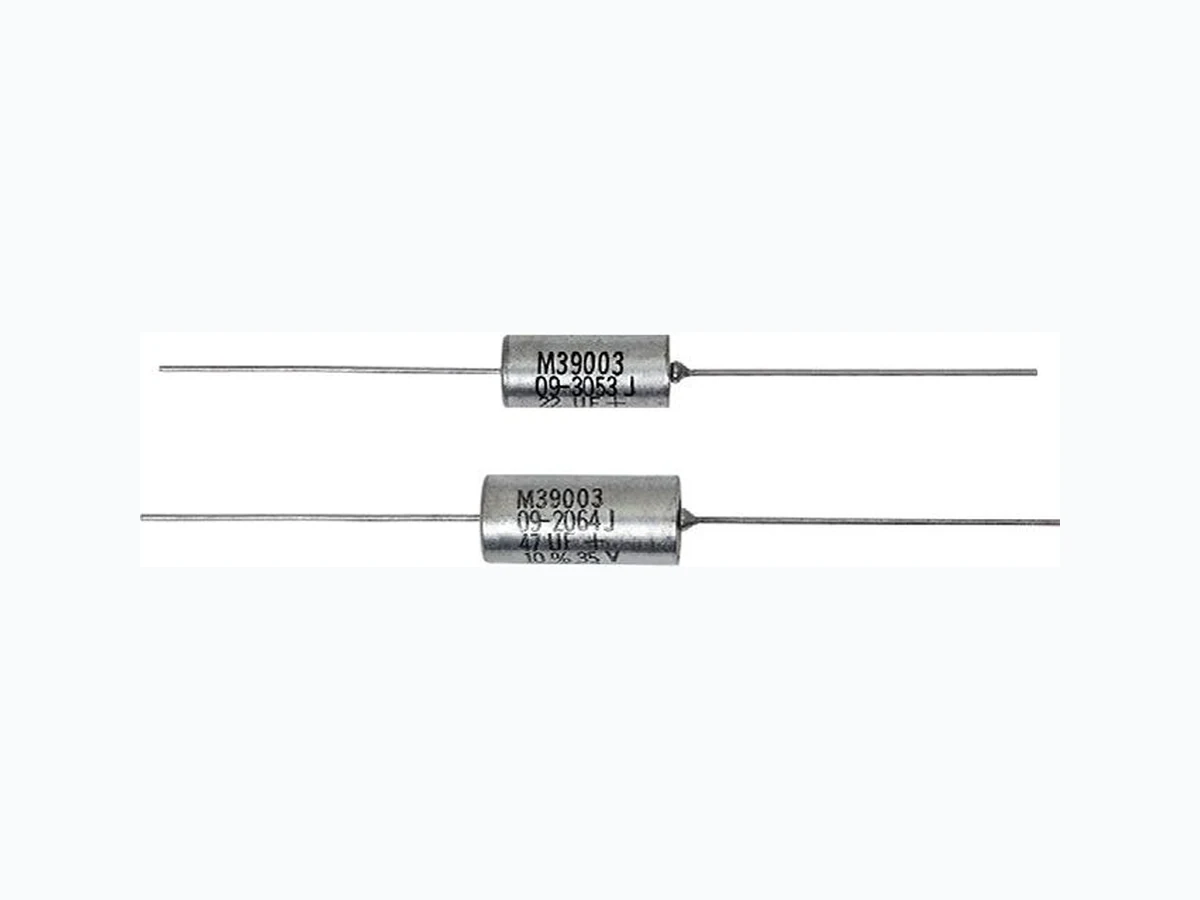
M39003 VISHAY
Document overview
- Manufacturer or author: Provided By www.digicamel.com(FREE DATASHEET DOWNLOAD SITE)
- PDF pages: 6
Technical content
www.vishay.com Vishay Revision: 05-Aug-2020 1 Document Number: 40158 For technical questions, contact: tantalum@vishay.com THIS DOCUMENT IS SUBJECT TO CHANGE WITHOUT NOTICE. THE PRODUCTS DESCRIBED HEREIN AND THIS DOCUMENT ARE SUBJECT TO SPECIFIC DISCLAIMERS, SET FORTH AT www.vishay.com/doc?91000 Solid-Electrolyte TANTALEX™ Capacitors, Military MIL-PRF-39003/09 Qualified, Style CSR21 PERFORMANCE CHARACTERISTICS Operating Temperature: -55 °C to +125 °C (above 85 °C, voltage derating is required) Capacitance Range: 5.6 μF to 330 μF Capacitance Tolerance: ± 5 %, ± 10 %, ± 20 % Voltage Rating: 6 V DC to 50 VDC
FEATURES
- Hermetically sealed
- Metal cased
- Axial lead
- Weibull failure rates B, C, D
- Exponential failure rates M, P, R, S
- L o w E S R
- 100 % surge current test
- Tape and reel available per EIA-296 standard STYLE, MILITARY SPECIFICATION SHEET Style CSR21, M39003/09 MIL-PRF-39003/9
DESCRIPTION
Solid-electrolyte T ANTALEX capacitors to military specification MIL-PRF-39003 - Exponential and Weibull Distribution: hermetically sealed, metal cased, axial leaded tubular capacitors manufactured as military style CSR21. These capacitors are furnished to the requirements of the military specification, including marking, testing and inspection. In accordance with the specification, all capacitors are marked with the military part number (M 39003/xx-xxxx) rather than the older style designation (CSRxxxxxxxx) and should be ordered as such . All capacitors covered by MIL-PRF-39003 are now ordere d with the military part number as illustrated in the Part Numbering System chart. Capacitors must not be or dered using the style number identification. MIL-PRF-39003 establishes failure rates (expressed in percent per 1000 h) based on exponential and Weibull distribution. Care must be exercised in ordering to insure the part number correctly identifies the desired failure rate level. In addition, each order for military style CSR13, CSR21, CSR23 capacitors requiring government inspection must state whether inspection is to be at the destination or at the Vishay plant. Orders requiring source inspection cannot be shipped until this has been accomplished. For information on the performance characteristics of these capacitors, please refer to th e latest issue of the military specification. Note (1) See detailed packaging information following the Standard Ratings table
ORDERING INFORMATION
BASIC SLASH SHEET DASH NUMBER SURGE CURRENT PACKAGING OPTION (1) DOCUMENT NUMBER OPTION LETTER Indicates the Basic Specification; in this case MIL-PRF-39003 Indicates the Specification Sheet of the Basic Military Specification Taken from Ratings table of the Specification Sheet Blank = standard, +25 °C, after Weibull B = -55 °C and +85 °C, after Weibull C = -55 °C and +85 °C, before Weibull E = -55 °C and +85 °C, after Weibull, high temperature solder F = -55 °C and +85 °C, before Weibull, high temperature solder H = +25 °C, after Weibull, high temperature solder Blank = bulk /TR = tape and reel, full reel /HR = tape and reel, half reel /PR = tape and reel, partial reel /RR = tape and reel, option R, full reel /WR = tape and reel, option W, full reel
www.vishay.com Vishay Revision: 05-Aug-2020 2 Document Number: 40158 For technical questions, contact: tantalum@vishay.com THIS DOCUMENT IS SUBJECT TO CHANGE WITHOUT NOTICE. THE PRODUCTS DESCRIBED HEREIN AND THIS DOCUMENT ARE SUBJECT TO SPECIFIC DISCLAIMERS, SET FORTH AT www.vishay.com/doc?91000 Notes
- The case insulation shal l extend 0.015" [0.38 mm] minimum beyond each end. However, when a shrink-fitted insulation is used, it shall lap over the ends of the capacitor body
- A minimum lead length of 1.0" [2.54 mm] for use with tape and reel automatic insertion equipment is available upon request DIMENSIONS in inches [millimeters] CASE CODE L ± 0.031 [0.79] D + 0.016 [0.41] - 0.015 [0.38] M ± 0.002 [0.05] J (MAX.) RATINGS AND CASE CODES μF 6 V 10 V 15 V 20 V 35 V 50 V 5.6 C 6.8 C 8.2 C 10 C 12 C 15 C 18 C 22 CD 27 CD 33 CD 39 CD 47 CD
56 C D
68 C D
82 C D
100 C D
120 C D
150 C D
180 C D
M J 1.500 ± 0.250 [38.10 ± 6.35] 0.094 [2.4] Max. L D
www.vishay.com Vishay Revision: 05-Aug-2020 3 Document Number: 40158 For technical questions, contact: tantalum@vishay.com THIS DOCUMENT IS SUBJECT TO CHANGE WITHOUT NOTICE. THE PRODUCTS DESCRIBED HEREIN AND THIS DOCUMENT ARE SUBJECT TO SPECIFIC DISCLAIMERS, SET FORTH AT www.vishay.com/doc?91000 STANDARD RATINGS CAPACITANCE (μF) CASE CODE CAP. TOL. (± %) PART NO. M39003/09- FAILURE RATE LEVEL (%/1000 h) MAX. DCL (μA) AT MAX. DF AT +25 °C 1 kHz (%) MAX. ESR AT +25 °C 100 kHz () DERATED MAX. RIPPLE CURRENT AT +25 °C (A) M 1.0 P 0.1 R 0.01 S 0.001 B 0.1 C 0.01 D 0.001 +25 °C +85 °C +125 °C 40 kHz 1 kHz
6 VDC AT +85 °C, SURGE = 8 V; 4 VDC AT +125 °C
180 C 5 0004 0104 0204 0304 2004 3004 4004 5.5 110 138 10 0.060 3.4 2.4 180 C 10 0005 0105 0205 0305 2005 3005 4005 5.5 110 138 10 0.060 3.4 2.4 270 D 5 0006 0106 0206 0306 2006 3006 4006 6.5 130 163 10 0.050 4.1 3.4 270 D 10 0007 0107 0207 0307 2007 3007 4007 6.5 130 163 10 0.050 4.1 3.4 330 D 5 0008 0108 0208 0308 2008 3008 4008 7.5 150 188 12 0.045 4.3 3.8 330 D 10 0009 0109 0209 0309 2009 3009 4009 7.5 150 188 12 0.045 4.3 3.8 330 D 20 0010 0110 0210 0310 2010 3010 4010 7.5 150 188 12 0.045 4.3 3.8 10 V DC AT +85 °C, SURGE = 13 V; 7 VDC AT +125 °C 100 C 5 0013 0113 0213 0313 2013 3013 4013 5.0 100 125 8 0.075 3.0 2.2 100 C 10 0014 0114 0214 0314 2014 3014 4014 5.0 100 125 8 0.075 3.0 2.2 100 C 20 0015 0115 0215 0315 2015 3015 4015 5.0 100 125 8 0.075 3.0 2.2 120 C 5 0016 0116 0216 0136 2016 3016 4016 6.0 120 150 8 0.070 3.2 2.5 120 C 10 0017 0117 0217 0317 2017 3017 4017 6.0 120 150 8 0.070 3.2 2.5 180 D 5 0018 0118 0218 0318 2018 3018 4018 9.0 180 226 8 0.060 3.7 3.4 180 D 10 0019 0119 0219 0319 2019 3019 4019 9.0 180 226 8 0.060 3.7 3.4 220 D 5 0020 0120 0220 0320 2020 3020 4020 10.0 200 250 10 0.055 3.9 3.4 220 D 10 0021 0121 0221 0321 2021 3021 4021 10.0 200 250 10 0.055 3.9 3.4 220 D 20 0022 0122 0222 0322 2022 3022 4022 10.0 200 250 10 0.055 3.9 3.4 15 V DC AT +85 °C, SURGE = 20 V; 10 VDC AT +125 °C 68 C 5 0025 0125 0225 0325 2025 3025 4025 5.0 100 125 6 0.095 2.7 2.2 68 C 10 0026 0126 0226 0326 2026 3026 4026 5.0 100 125 6 0.095 2.7 2.2 68 C 20 0027 0127 0227 0327 2027 3027 4027 5.0 100 125 6 0.095 2.7 2.2 120 D 5 0028 0128 0228 0328 2028 3028 4028 9.0 180 226 8 0.070 3.5 2.8 120 D 10 0029 0129 0229 0329 2029 3029 4029 9.0 180 226 8 0.070 3.5 2.8 150 D 5 0030 0130 0230 0330 2030 3030 4030 10.0 200 250 8 0.065 3.6 3.1 150 D 10 0031 0131 0231 0331 2031 3031 4031 10.0 200 250 8 0.065 3.6 3.1 150 D 20 0032 0132 0232 0332 2032 3032 4032 10.0 200 250 8 0.065 3.6 3.1 20 V DC AT +85 °C, SURGE = 26 V; 13 VDC AT +125 °C
www.vishay.com Vishay Revision: 05-Aug-2020 4 Document Number: 40158 For technical questions, contact: tantalum@vishay.com THIS DOCUMENT IS SUBJECT TO CHANGE WITHOUT NOTICE. THE PRODUCTS DESCRIBED HEREIN AND THIS DOCUMENT ARE SUBJECT TO SPECIFIC DISCLAIMERS, SET FORTH AT www.vishay.com/doc?91000
20 VDC AT +85 °C, SURGE = 26 V; 13 VDC AT +125 °C
56 D 5 0043 0143 0243 0343 2043 3043 4043 5.5 110 138 6 0.100 2.9 2.2 56 D 10 0044 0144 0244 0344 2044 3044 4044 5.5 110 138 6 0.100 2.9 2.2 68 D 5 0045 0145 0245 0345 2045 3045 4045 7.0 140 175 6 0.095 3.0 2.4 68 D 10 0046 0146 0246 0346 2046 3046 4046 7.0 140 175 6 0.095 3.0 2.4 68 D 20 0047 0147 0247 0347 2047 3047 4047 7.0 140 175 6 0.095 3.0 2.4 82 D 5 0048 0148 0248 0348 2048 3048 4048 8.0 160 200 6 0.085 3.1 2.5 82 D 10 0049 0149 0249 0349 2049 3049 4049 8.0 160 200 6 0.085 3.1 2.5 100 D 5 0050 0150 0250 0350 2050 3050 4050 10.0 200 250 8 0.075 3.3 2.5 100 D 10 0051 0151 0251 0351 2051 3051 4051 10.0 200 250 8 0.075 3.3 2.5 100 D 20 0052 0152 0252 0352 2052 3052 4052 10.0 200 250 8 0.075 3.3 2.5 35 V DC AT +85 °C, SURGE = 46 V; 23 VDC AT +125 °C 33 D 5 0058 0158 0258 0358 2058 3058 4058 5.5 110 138 5 0.130 2.5 1.9 33 D 10 0059 0159 0259 0359 2059 3059 4059 5.5 110 138 5 0.130 2.5 1.9 33 D 20 0060 0160 0260 0360 2060 3060 4060 5.5 110 138 5 0.130 2.5 1.9 39 D 5 0061 0161 0261 0361 2061 3061 4061 7.0 140 175 5 0.120 2.6 2.0 39 D 10 0062 0162 0262 0362 2062 3062 4062 7.0 140 175 5 0.120 2.6 2.0 47 D 5 0063 0163 0263 0363 2063 3063 4063 8.0 160 200 5 0.110 2.7 2.2 47 D 10 0064 0164 0264 0364 2064 3064 4064 8.0 160 200 5 0.110 2.7 2.2 47 D 20 0065 0165 0265 0365 2065 3065 4065 8.0 160 200 5 0.110 2.7 2.2 50 V DC AT +85 °C, SURGE = 65 V; 33 VDC AT +125 °C 22 D 5 0083 0183 0283 0383 2083 3083 4083 5.5 110 138 4 0.160 2.3 1.7 22 D 10 0084 0184 0284 0384 2084 3084 4084 5.5 110 138 4 0.160 2.3 1.7 22 D 20 0085 0185 0285 0385 2085 3085 4085 5.5 110 138 4 0.160 2.3 1.7 STANDARD RATINGS CAPACITANCE (μF) CASE CODE CAP. TOL. (± %) PART NO. M39003/09- FAILURE RATE LEVEL (%/1000 h) MAX. DCL (μA) AT MAX. DF AT +25 °C 1 kHz (%) MAX. ESR AT +25 °C 100 kHz () DERATED MAX. RIPPLE CURRENT AT +25 °C (A) M 1.0 P 0.1 R 0.01 S 0.001 B 0.1 C 0.01 D 0.001 +25 °C +85 °C +125 °C 40 kHz 1 kHz
www.vishay.com Vishay Revision: 05-Aug-2020 5 Document Number: 40158 For technical questions, contact: tantalum@vishay.com THIS DOCUMENT IS SUBJECT TO CHANGE WITHOUT NOTICE. THE PRODUCTS DESCRIBED HEREIN AND THIS DOCUMENT ARE SUBJECT TO SPECIFIC DISCLAIMERS, SET FORTH AT www.vishay.com/doc?91000 STANDARD PACKAGING QUANTITY CASE CODE QUANTITY (pcs/reel) BULK QUANTITY FULL REEL /TR; /RR; /WR HALF REEL /HR PARTIAL REEL /PR PER TRAY PER BOX C 500 250 100 20 100 D 500 250 100 20 80 INSIDE TAPE SPACING PACKAGING OPTION CASE CODE TAPE SPACING /TR; /HR; /PR C, D 2.88 ± 0.02 [73.0 ± 0.51] /RR C, D 2.47 ± 0.02 [62.7 ± 0.51] /WR C, D 2.05 ± 0.02 [52.1 ± 0.51] PRODUCT INFORMATION Quick Reference Guide www.vishay.com/doc?40037 Selector Guide www.vishay.com/doc?49054 Parameter Comparison Guide www.vishay.com/doc?40033 Mounting of Through-Hole Components www.vishay.com/doc?40108 Frequently Asked Questions www.vishay.com/doc?40110 Solid Tantalum Capacitors (With MnO2 Electrolyte) Voltage Derating www.vishay.com/doc?40246
www.vishay.com Vishay Revision: 01-Jan-2021 1 Document Number: 91000 Disclaimer ALL PRODUCT, PRODUCT SPECIFICATIONS AND DATA AR E SUBJECT TO CHANGE WITH OUT NOTICE TO IMPROVE RELIABILITY, FUNCTION OR DESIGN OR OTHERWISE. Vishay Intertechnology, Inc., its affiliates, agents, and employee s, and all persons acting on it s or their behalf (collectivel y, “Vishay”), disclaim any and all liability for any errors, inaccuracies or incompleteness contained in any datasheet or in any other disclosure relating to any product. Vishay makes no warranty, representation or guarantee regarding the suitability of the products for any particular purpose or the continuing production of any product. To the maximum extent permitted by applicable law, Vishay disclaims (i) any and all liability arising out of the application or use of any product , (ii) any and all liability, including without limitation specia l, consequential or incidental damages, and (iii) any and all implied warranties, incl uding warranties of fitness for particular purpose, non-infringement and merchantability. Statements regarding the suitability of products for certain types of applicatio ns are based on Vishay’s knowledge of typical requirements that are often placed on Vishay products in generic applications. Such statements are not binding statements about the suitability of products for a particular applic ation. It is the customer’s responsibility to validate tha t a particular product with the prope rties described in the product sp ecification is suitable for use in a particular application. Parameters provided in datasheets and / or specifications may vary in different ap plications and performance may vary over time. All operating parameters, including typical parameters, must be validated for each customer application by the customer’s technical experts. Product specifications do not expand or otherwise modify Vishay’s term s and conditions of purchase, including but not limited to the warranty expressed therein. Except as expressly indicated in writing, Vishay products are not designed for use in medical, life-saving, or life-sustaining applications or for any other application in which the failure of the Vishay product could result in personal injury or death. Customers using or selling Vishay product s not expressly indicated for use in such applications do so at their own risk. Please contact authorized Vishay personnel to obtain writ ten terms and conditions rega rding products designed for such applications. No license, express or implied, by estoppel or otherwise, to any intellectual property rights is gr anted by this document or by any conduct of Vishay. Product names and markings noted herein may be trademarks of their respective owners. © 2021 VISHAY INTERTECHNOLOGY, INC. ALL RIGHTS RESERVED