


 Download PDF
M2EXDY MSYSTEM
Document overview
- PDF pages: 6
Technical content
Page 1
Super-mini Signal Conditioners with Display Mini-M M2E Series
CURRENT LOOP SUPPLY
(PC programmable)
[1] POWER INPUT
AC Power M2: 100 – 240 V AC (Operational voltage range 85 – 264 V, 47 – 66 Hz) DC Power R: 24 V DC
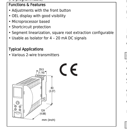
MODEL: M2EXDY–[1][2]
ORDERING INFORMATION
- Code number: M2EXDY-[1][2] Specify a code from below for each [1] and [2]. (e.g. M2EXDY-M2/Q)
- Specify the specification for option code /Q (e.g. /C01/S01/SET)
INPUT
Current 4 – 20 mA DC (Input resistance 250 Ω) (Selectable within 0 – 20 mA DC)
OUTPUT – Field-selectable
◆ DC Output
- Current output: 0 - 20 mA DC
- Voltage output: -5 - +5 V DC
- Voltage output: -10 - +10 V DC
(Operational voltage range 24 V ±10 %, ripple 10 %p-p max.) P: 110 V DC (Operational voltage range 85 – 150 V, ripple 10 %p-p max.)
[2] OPTIONS
blank: none /Q: With options (specify the specification)
SPECIFICATIONS OF OPTION: Q (multiple selections) COATING (For the detail, refer to M-System's web site.) /C01: Silicone coating /C02: Polyurethane coating /C03: Rubber coating
TERMINAL SCREW MATERIAL
/S01: Stainless steel
EX-FACTORY SETTING
/SET: Preset according to the Ordering Information Sheet (No. ESU-5170) Default setting will be used if not otherwise specified.
RELATED PRODUCTS
- M2E configurator software (model: M2ECFG) Downloadable at M-System’s web site. A dedicated cable is required to connect the module to the PC. Please refer to the internet software download site or the users manual (EM-5147) for the M2E configurator for applicable cable types.
GENERAL SPECIFICATIONS
Construction: Plug-in Connection: M3 screw terminals (torque 0.8 N·m) Screw terminal: Chromated steel (standard) or stainless steel Housing material: Flame-resistant resin (gray) Isolation: Input to output to power Overrange output: Approx. -7.5 to +107.5 % (Not available for current output not greater than 0 mA) Zero adjustment: -5 to +5 % (front) Span adjustment: 95 to 105 % (front) Output setting: DIP Switch on side panel (refer to the instruction manual) Configuration: Program with front buttons or Via PC. Programmable features include: Refer to the parameter list. Configurator connection: 2.5 dia. miniature jack;
M2EXDY SPECIFICATIONS
ES-5170 Rev.1 Page 1/6
Page 2
RS-232-C level
DISPLAY
Display functions: Displays and sets measured range, engineering unit Display size: Approx. 15.6 × 20.8 mm (0.61” × 0.82”) Number of pixels: 68 × 95 (horizontal × vertical) Character color: Yellow Display life: Approx. 60000 hours (Expected time for the Display brightness to be reduced to 50 % when the Display is used continuously with brightness setting 2 in 25 ℃) Display type: OEL display Display digit: Negative 5 digits, positive 6 digits (-99999 to 999999) Decimal point position: Selectable
SUPPLY OUTPUT
■ SUPPLY OUTPUT (across the terminals 1 – 2) Output voltage: 24 – 28 V DC with no load 19 V DC minimum at 20 mA Current rating: ≤ 22 mA DC Permissible load resistance: LR (Ω) ≤ (19 – Min. Operational Voltage)V ÷ 0.02 A
- Shortcircuit Protection Current limited: 35 mA max. Protected time duration: No limit
INPUT SPECIFICATIONS
■ DC Current Input resistance: Incorporated (250 Ω) Input range: 0 - 20 mA DC Minimum span: 1 mA DC The measurement available for -7.5 - +107.5% of input setting range.
OUTPUT SPECIFICATIONS
■ DC Current Output range: 0 – 20 mA DC Conformance range: 0 – 21.5 mA DC Minimum span: 1 mA Offset: Lower range can be any specific value within the output range provided that the minimum span is maintained. Load resistance: Output drive 15 V max. (Not available to output less than 0 mA, output range may not be extended to -7.5 %) ■ DC Voltage Output range: -5 - +5 V DC, -10 - +10 V DC Conformance range: -5.75 - +5.75 V DC, -11.5 - +11.5 V DC
Minimum span: 250 mV, 1 V Offset: Lower range can be any specific value within the output range provided that the minimum span is maintained. Load resistance: Output drive 1 mA max.
LINEARIZATION
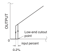
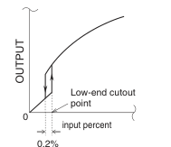
■ Linearization Types Linear: Proportional to the input Square root: The input is square root extracted. User's table: Segment linearization Calibration points: Max. 128 points; the input % and linearized value in scaling are specified in pairs. Selectable range: -7.5 to +107.5 % as input %; -7.5 to +107.5 % as output) ■ Low-end Cutout:Low-end cutout (Low Cut) point selectable within the range of 0 to 100 %. With linear or segment linearization, the output signal is forcibly set to 0 % for the input lower than the low-cut point. With the square root extraction, the output signal is linear to the input when the latter is lower than the low-cut point.
- Square Root
- Linear or User Table
INSTALLATION
Power Consumption
- AC: ≤ 7 VA at 100 V ≤ 10 VA at 200 V ≤ 12 VA at 264 V
- DC: ≤ 4 W Operating temperature: -5 to +55°C (23 to 131°F) Operating humidity: 10 to 85 %RH (non-condensing) Mounting: Surface or DIN rail Weight: Approx. 200 g (0.44 lb)

M2EXDY SPECIFICATIONS
ES-5170 Rev.1 Page 2/6
Page 3
PERFORMANCE
Accuracy: Input accuracy + output accuracy

See CALCULATION EXAMPLES OF OVERALL ACCURACY. Inversely proportional to the setting span. Except the accuracy of input resistor. Input accuracy: (% of max. input range) Input accuracy differs depending on the linearization type. Linear: ±(0.04 % of FS) Square root extraction (1 % or more of input): ±(0.1 % of FS) Segment linearization: ±(0.04 % of FS) [gain ≤ 1] ±(0.04 % x gain of FS) [gain > 1] Display accuracy: Input display: Input accuracy ±1 digit Output display: Input accuracy + output accuracy ±1 digit Output accuracy: ±0.04 % of max. output range Temp. coefficient (% of max. I/O range): ±0.015 %/°C (±0.008 %/°F) Response time (filter time constant: 0 sec.): ≤ 0.5 sec.
(0 – 90 %) Line voltage effect: ±0.1 % over voltage range Insulation resistance: ≥ 100 MΩ with 500 V DC Dielectric strength: 2000 V AC @1 minute (input to output to power to ground)
CALCULATION EXAMPLES OF OVERALL ACCURACY
[Example] Input Range: 0 – 20 mA, Input Setting: 4 – 20 mA, Output Range: 0 – 20 mA, Output Setting: 4 – 20 mA (when the linearization type is linear) ■ Overall accuracy
- Input Accuracy = Input Range Span (20 mA) ÷ Input Span Setting (16 mA) × 0.04 % = 0.05 %
- Output Accuracy = Output Range Span (20 mA) ÷ Output Span Setting (16 mA) × 0.04 % = 0.05 % Overall Accuracy = 0.05 + 0.05 = ±0.10 %
STANDARDS & APPROVALS
EU conformity: EMC Directive EMI EN 61000-6-4 EMS EN 61000-6-2 Low Voltage Directive EN 61010-1 Installation Category II Pollution Degree 2 Input or output to power: Reinforced insulation (300 V) Input to output: Basic insulation (300 V) RoHS Directive EN 50581
M2EXDY SPECIFICATIONS
ES-5170 Rev.1 Page 3/6
Page 4
EXTERNAL VIEW
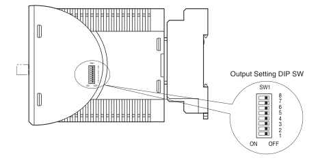
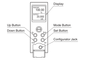
| COMPONENT | FUNCTION |
| Display | Indicates present values, setting values and abnormal information. Two types of present values at upper and lower are displayed by setting. |
| Mode Button | Used to shift from measuring mode to each setting mode. Destination to shift is changed by the time pressing and holding the button. Used to return from each setting mode to measuring mode. (press and hold for 2 sec. or more) |
| Set Button | Used to change setting value of setting parameter. When at setting changeable state, used to enter (save) the setting value. Used to move on through digits of setting value for input/output scaling at setting changeable state, |
| Up Button | Used to shift through setting parameter, and to increase or select setting value. |
| Down Button | Used to shift through setting parameter, and to decrease or select setting value. |
| Conf gurator Jack | Used to conf gure with M2E conf gurator software (model: M2ECFG). At the same time, set the lockout setting of the unit to ‘lock.’ |
Refer to the operating manual (EM-5170-B) for detailed procedures.
M2EXDY SPECIFICATIONS
ES-5170 Rev.1 Page 4/6
Page 5
PARAMETER LIST
It is available to conf gure or conf rm settings shown below by using front button. Conf guring or conf rming with PC is available when using M2E conf gurator software (model: M2ECFG).
| MODE | ITEM | SETTING PARAMETER | RANGE | UNIT | INITIAL VALUE |
|---|---|---|---|---|---|
| Basic setting | 01 | Lockout setting | Lock / Unlock | — | Lock |
| 12 | 0 % input setting | 0.00 – 19.00 | mA | 4.00 | |
| 13 | 100 % input setting | 1.00 – 20.00 | mA | 20.00 | |
| 14 | 0 % input scaling | -99999 – 999999 | — | 0.00 | |
| 15 | 100 % input scaling | -99999 – 999999 | — | 100.00 | |
| 16 | Input decimal point | No decimal point The number of decimal places: 1 – 5 | — | 2 places of decimals | |
| 17 | Output range | 0 – 20 mA -5 – +5 V -10 – +10 V | — | 0 – 20 mA | |
| 18 | 0 % output setting | 0.000 – 19.000 -5.000 – 4.750 -10.000 – 9.000 | mA V V | 4.000 | |
| 19 | 100 % output setting | 1.000 – 20.000 -4.750 – 5.000 -9.000 – 10.000 | mA V V | 20.000 | |
| 20 | 0 % output scaling | -99999 – 999999 | — | 0.00 | |
| 21 | 100 % output scaling | -99999 – 999999 | — | 100.00 | |
| 22 | Output decimal point | No decimal point The number of decimal places: 1 – 5 | — | 2 places of decimals | |
| 26 | Loop test | -7.50 – 107.50 | % | Cancel | |
| Option | 54 | Low cut | Disable / Enable | — | Disable |
| 55 | Low cut point | 0.00 – 100.00 | % | 0.00 | |
| 60 | Unit (INP Scaling) | Choose from 68 types* | — | % | |
| 61 | Unit (OUT Scaling) | Choose from 68 types* | — | % | |
| 67 | Filter time constant | 0 – 30 | sec. | 0 | |
| 69 | Input Zero f ne adjust | -5.000 – 5.000 | % | 0.000 | |
| 70 | Input Span f ne adjust | 95.000 – 105.000 | % | 100.000 | |
| 71 | Output Zero f ne adjust | -5.000 – 5.000 | % | 0.000 | |
| 72 | Output Span f ne adjust | 95.000 – 105.000 | % | 100.000 | |
| 01 | Lockout setting | Lock / Unlock | — | Lock | |
| Advanced | 90 | Display setting | Upper: choose from 5 types* Lower: choose from 6 types* | — | Upper: INPUT Lower: PERCENT |
| 91 | Brightness | 1 (darkest) – 4 (brightest) | — | 4 | |
| 92 | Display timeout | 0 (always on), 1 – 60 | min. | 10 | |
| 93 | Reset all settings | OFF / RESET | — | OFF | |
| 94 | Version indication | — | — | — | |
| 01 | Lockout setting | Lock / Unlock | — | Lock | |
| Linearization | 100 | Linearization | Linear, Square root, User’s table | — | Linear |
| 166 | Number of points | 2 – 128 | — | 2 | |
| 167 – 422 | Table | -7.50 – 107.50 | % | X001 -7.50 Y001 -7.50 X002 107.50 Y002 107.50 | |
| 01 | Lockout setting | Lock / Unlock | — | Lock |
\* For detailed types, refer to the operating manual (EM-5170-B).
M2EXDY SPECIFICATIONS
ES-5170 Rev.1 Page 5/6
Page 6
EXTERNAL DIMENSIONS & TERMINAL ASSIGNMENTS unit: mm (inch)
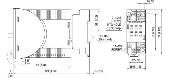
29 (1.14)
- When mounting, no extra space is needed between units.
SCHEMATIC CIRCUITRY & CONNECTION DIAGRAM
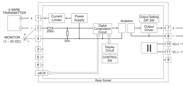
OUTPUT
POWER
■ When Used as Current Input
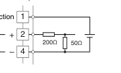
No Connection
INPUT
