


 Download PDF
DATASHEET SEARCH SITE
Document overview
- PDF pages: 11
Technical content
Page 1

Date:- 20 Oct 2014
Data Sheet Issue:- 2
Soft Recovery Diode
Type M1494NC180 to M1494NC250
Absolute Maximum Ratings
| VOLTAGE RATINGS | MAXIMUM LIMITS | UNITS | |
|---|---|---|---|
| VRRM VRSM | Repetitive peak reverse voltage, (note 1) Non-repetitive peak reverse voltage, (note 1) | 1800-2500 1900-2600 | V V |
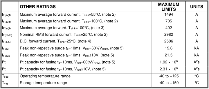
Notes:- 1) De-rating factor of 0.13% per °C is applicable for Tj below 25°C. 2) Double side cooled, single phase; 50Hz, 180° half-sinewave. 3) Single side cooled, single phase; 50Hz, 180° half-sinewave. 4) Double side cooled. 5) Half-sinewave, 125°C Tj initial.
Page 1 of 11
Page 2
Characteristics
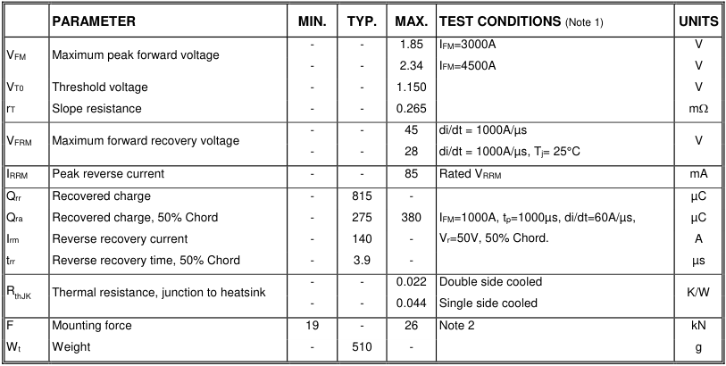
Notes:- 1) Unless otherwise indicated Tj=125°C. 2) For other clamp forces, please consult factory.
Page 2 of 11
Page 3
Notes on Ratings and Characteristics
1.0 Voltage Grade Table
| Voltage Grade | V RRM (V) | V RSM (V) | V dc R (V) |
| 18 | 1800 | 1900 | 1150 |
| 20 | 2000 | 2100 | 1250 |
| 22 | 2200 | 2300 | 1350 |
| 24 | 2400 | 2500 | 1450 |
| 25 | 2500 | 2600 | 1500 |
2.0 De-rating Factor
A blocking voltage de-rating factor of 0.13% per °C is applicable to this device for Tj below 25°C.
3.0 ABCD Constants
These constants (applicable only over current range of VF characteristic in Figure 1) are the coefficients of the expression for the forward characteristic given below:
V A B ln(I
) C I D I
F
F
F
F
where IF = instantaneous forward current.
4.0 Reverse recovery ratings
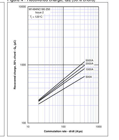
(i) Qra is based on 50% Irm chord as shown in Fig.(a) below.
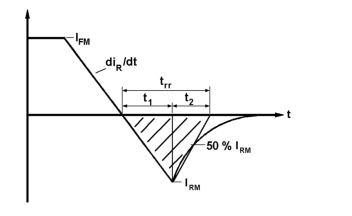
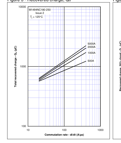
(ii) Qrr is based on a 150s integration time.
150 s i . Q
dt
rr rr
I.e.
0 t 1
K Factor
(iii)
t 2
Page 3 of 11
Page 4
5.0 Reverse Recovery Loss
The following procedure is recommended for use where it is necessary to include reverse recovery loss.
From waveforms of recovery current obtained from a high frequency shunt (see Note 1) and reverse voltage present during recovery, an instantaneous reverse recovery loss waveform must be constructed. Let the area under this waveform be E joules per pulse. A new sink temperature can then be evaluated from:
J MAX
th JK
T T
E k f R
( )
( )
SINK
Where k = 0.2314 (°C/W)/s
E = Area under reverse loss waveform per pulse in joules (W.s.) f = Rated frequency in Hz at the original sink temperature. Rth(J-Hs) = d.c. thermal resistance (°C/W)
The total dissipation is now given by:
W
W
E f
(tot)
(original )
NOTE 1 - Reverse Recovery Loss by Measurement
This device has a low reverse recovered charge and peak reverse recovery current. When measuring the charge, care must be taken to ensure that:
(a) AC coupled devices such as current transformers are not affected by prior passage of high amplitude forward current.
(b) A suitable, polarised, clipping circuit must be connected to the input of the measuring oscilloscope to avoid overloading the internal amplifiers by the relatively high amplitude forward current signal.
(c) Measurement of reverse recovery waveform should be carried out with an appropriate critically damped snubber, connected across diode anode to cathode. The formula used for the calculation of this snubber is shown below:
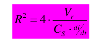
Where: Vr = Commutating source voltage CS = Snubber capacitance R = Snubber resistance
6.0 Snubber Components
When selecting snubber components, care must be taken not to use excessively large values of snubber capacitor or excessively small values of snubber resistor. Such excessive component values may lead to device damage due to the large resultant values of snubber discharge current. If required, please consult the factory for assistance.
Page 4 of 11
Page 5
7.0 Computer Modelling Parameters
7.1 Device Dissipation Calculations
2 4
V V ff r W
o o
s AV
I AV
2 2 ff r s
Where VT0 =1.15V, rT = 0.265m
ff = form factor (normally unity for fast diode applications)
T WAV R th
T T
T j(MAX )
K
7.2 Calculation of VF using ABCD Coefficients
The forward characteristic IF Vs VF, on page 6 is represented in two ways; the well established VT0 and rT tangent used for rating purposes and (i) a set of constants A, B, C, and D forming the coefficients of the representative equation for VF in ((iiii)) terms of IF given below:
V A B ln(I
) C I D I
F
F
F
F
The constants, derived by curve fitting software, are given in this report for hot characteristics. The resulting values for VF agree with the true device characteristic over a current range, which is limited to that plotted.
| 25°C Coefficients | 125°C Coefficients | |
| A | 0.6059922 | -0.0548532 |
| B | 0.0483707 | 0.1612135 |
| C | 9.492610×10⁻⁵ | 2.274044×10⁻⁴ |
| D | 0.0112304 | 2.917716×10⁻⁴ |
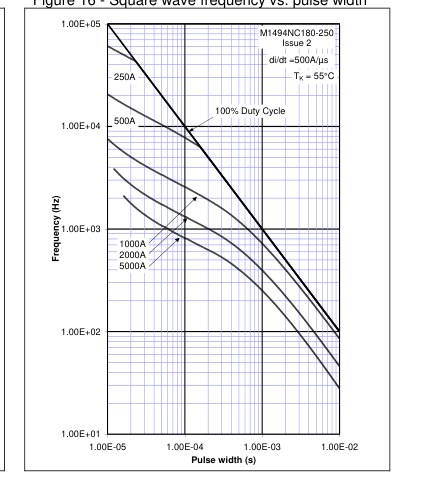
8.0 Frequency Ratings
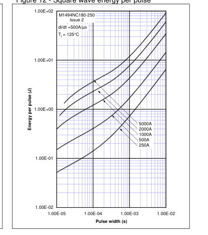
The curves illustrated in figures 8 to 16 are for guidance only and are superseded by the maximum ratings shown on page 1.
9.0 Square wave ratings
These ratings are given for load component rate of rise of forward current of 100 and 500 A/µs.
10.0 Duty cycle lines
The 100% duty cycle is represented on all the ratings by a straight line. Other duties can be included as parallel to the first.
Page 5 of 11
Page 6
Curves
Figure 1 – Forward characteristics of Limit device
Figure 2 – Maximum forward recovery voltage
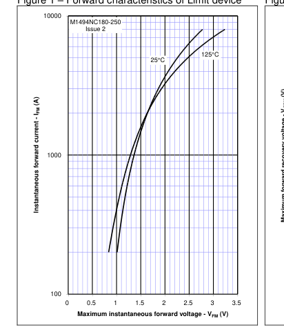
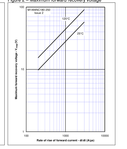
Figure 4 - Recovered charge, Qra (50% chord)
Figure 3 - Recovered charge, Qrr
Page 6 of 11
Page 7
Figure 5 - Maximum reverse current, Irm
Figure 6 - Maximum recovery time, trr (50% chord)
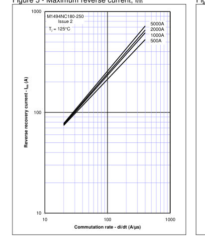
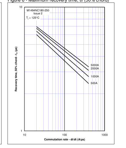
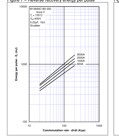
Figure 7 – Reverse recovery energy per pulse
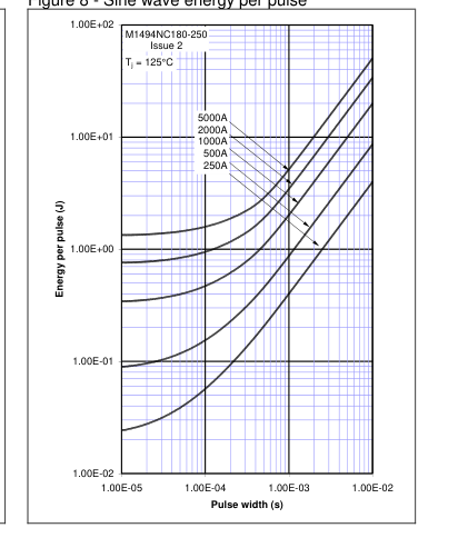
Figure 8 - Sine wave energy per pulse
Page 7 of 11
Page 8
Figure 9 - Sine wave frequency vs. pulse width
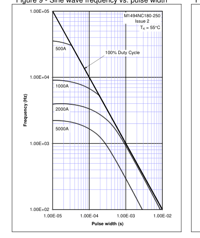
Figure 11 - Square wave energy per pulse
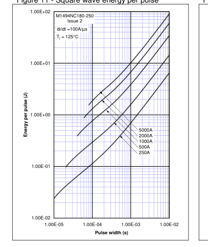
Figure 10 - Sine wave frequency vs. pulse width
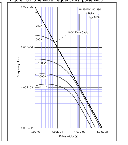
Figure 12 - Square wave energy per pulse
Page 8 of 11
Page 9
Figure 13 - Square wave frequency vs. pulse width
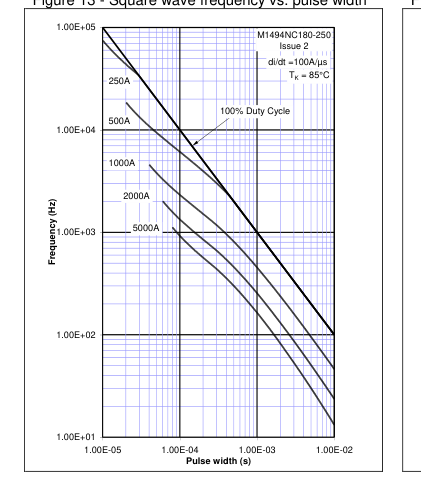
Figure 15 - Square wave frequency vs. pulse width
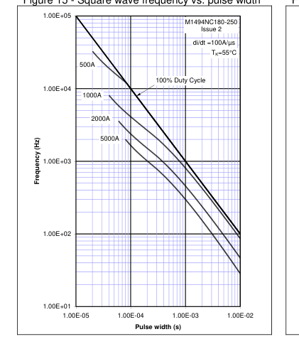
Figure 14 - Square wave frequency vs. pulse width
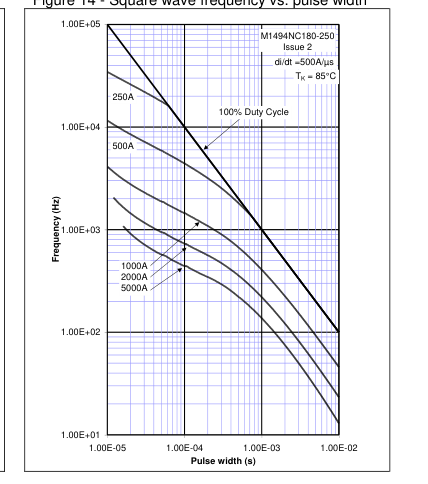
Figure 16 - Square wave frequency vs. pulse width
Page 9 of 11
Page 10
Figure 17 – Maximum surge and I2t ratings
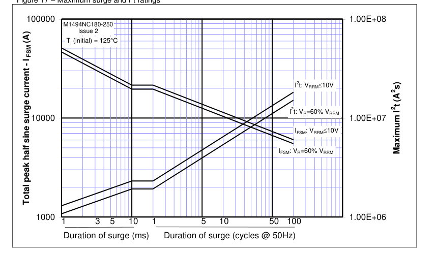
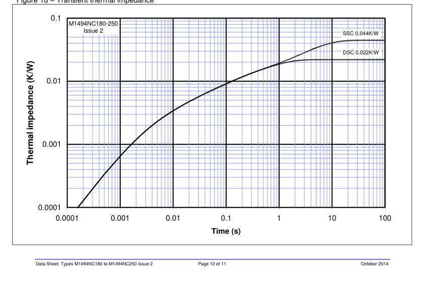
Figure 18 – Transient thermal impedance
Page 11
Outline Drawing & Ordering Information
(Please quote 10 digit code as below)
ORDERING INFORMATION
M1494
NC
Voltage code
Fixed
Fixed
VDRM/100
Type Code
outline code
18-25
Order code: M1494NC180 – 1800V VRRM, 27.7mm clamp height capsule.

IXYS Semiconductor GmbH Edisonstraße 15 D-68623 Lampertheim Tel: +49 6206 503-0 Fax: +49 6206 503-627 E-mail: marcom@ixys.de
IXYS Corporation 1590 Buckeye Drive
www.ixysuk.com
Milpitas CA 95035-7418 Tel: +1 (408) 547 9000 Fax: +1 (408) 496 0670
www.ixys.com
E-mail: sales@ixys.net
The information contained herein is confidential and is protected by Copyright. The information may not be used or disclosed except with the written permission of and in the manner permitted by the proprietors IXYS UK Westcode Ltd. In the interest of product improvement, IXYS UK Westcode Ltd reserves the right to change specifications at any time without prior notice. Devices with a suffix code (2-letter, 3-letter or letter/digit/letter combination) added to their generic code are not necessarily subject to the conditions and limits contained in this report.
Page 11 of 11
0
Fixed code
IXYS UK Westcode Ltd Langley Park Way, Langley Park, Chippenham, Wiltshire, SN15 1GE. Tel: +44 (0)1249 444524 Fax: +44 (0)1249 659448 E-mail: sales@ixysuk.com
IXYS Long Beach, Inc IXYS Long Beach, Inc 2500 Mira Mar Ave, Long Beach
CA 90815 Tel: +1 (562) 296 6584 Fax: +1 (562) 296 6585 E-mail: service@ixyslongbeach.com
© IXYS UK Westcode Ltd.