
LT3669-2 LINER
Document overview
- Manufacturer or author: Provided By www.digicamel.com(FREE DATASHEET DOWNLOAD SITE)
- PDF pages: 12
Technical content
Description
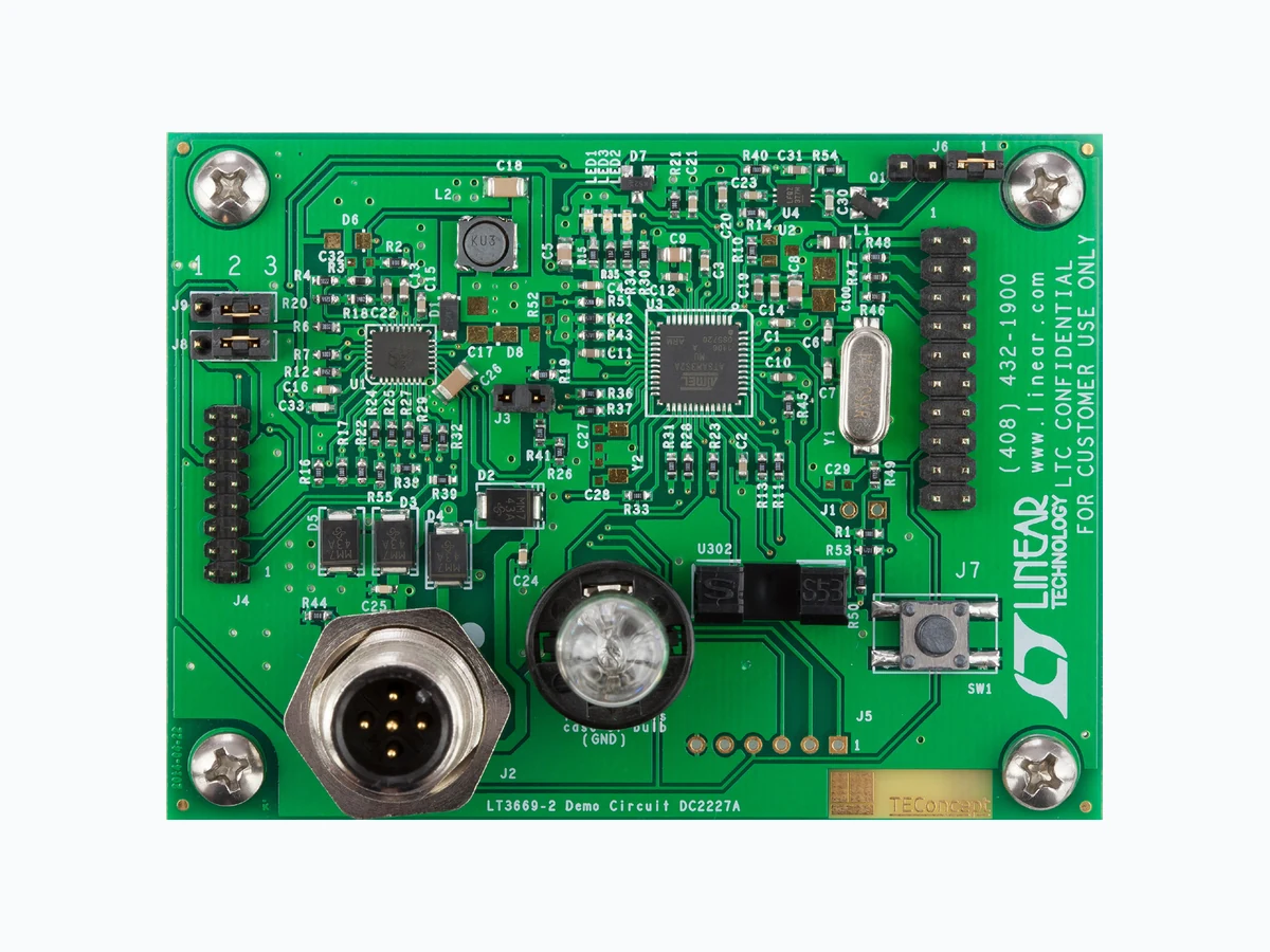
IO-Link Device with Multiple Sensors Demonstration circuit 2227A is a complete IO-Link ® de- vice built using the LT®3669-2 to implement an IO-Link v1.1 physical interface (PHY). The IO-Link stack protocol runs on an Atmel ATmega microcontroller which connects to LT3669-2’s logic IO-signals to communicate with an IO-Link master via the CQ1 transceiver. An LTC2997 temperature sensor, an opto-coupler (light barrier) and a pushbutton demonstrate IO-Link device functionality and master-slave interoperability. L, L T , L TC, L TM, Linear Technology and the Linear logo are registered trademarks of Linear Technology Corporation. IO-Link is a registered trademark of PROFIBUS User Organization (PNO). All other trademarks are the property of their respective owners. performance summary BoarD photo A 28V/100mA light bulb connected to LT3669-2’s second driver (Q2) demonstrates its high current driving capabili- ties. All low voltage circuitry is supplied by the LT3669-2’s integrated buck and LDO for high efficiency. Design files for this circuit board are available at http://www.linear.com/demo/DC2227A Specifications are at TA = 25°C, VL+ = 24V SYMBOL PARAMETER CONDITIONS MIN TYP MAX UNITS L+ Input Supply 18 36 V VBUCK LT3669-2's Buck Output Voltage 3.8 4 4.2 V VLDO LT3669-2's LDO Output Voltage 3.135 3.3 3.465 V
Additional Hardware and Software Requirements To operate the DC2227A demo circuit in IO-Link mode, additional hardware and software are required:
- PC running Windows XP or later with Ethernet Card. Alternatively a USB-to-Ethernet adaptor can also be used
- LT C IO-Link Master Demo Circuit DC2228A
- DC2228A Control Tool Software
- PoE Injector or 24V Power Supply
- DC2227A IODD Files (COM2 and COM3) Set-up Preparation (See Figures 1 and 2) Download and install the DC2228A Control Tool soft- ware from: www.linear.com/demo/DC2228A 2. Connect the DC2228A to power and the host com - puter. Refer to the DC2228A demo manual for detailed information about the different configuration options to supply the DC2228A and interface it to the PC. 3. Using a 3-wire IO-Link cable of up to 20m in length with M12 connectors, plug the male terminal to one of the 8-ports of the DC2228A (for example port 2 like in Figure 1) and the female terminal to the DC2227A. 4. Run the DC2228A Control Tool on the PC and connect to the DC2228A. See the DC2228A demo manual for detailed information of how to select the DC2228A as the master, configure the IP parameters and establish communication between the host computer and the master. Operation in IO-Link Mode (See Figures 1 and 2) 5. Download the DC2227A IODD files from: www.linear.com/demo/DC2227A 6. Click on the “Select Device” button and import the IODD files by selecting the downloaded xml files and then clicking on the “Import” button (one at a time). Operation in COM2 Click on the “Select Device” button again, this time making sure the correct port is selected. Use the fol- lowing IODD file: TEConcept_GmbH-65538-<Y YYYMMDD>-IODD1.1.xml 8. If the device is off, switch it on, enabling the L+ sup- ply of the connected master’s port by pressing the “Power ON” button keeping the light barrier open during power-up. If the device was already powered on coming from COM3 mode, power cycle it keeping the light barrier open to restart the device in COM2 mode. See the Light Barrier section for more information. 9. Start IO -Link communication by pressing the “IO-Link” button. The “Min. Cycle Time” is set to 20ms. 10. If a different IODD file is to be selected, stop IO-Link communication first by pressing the “Inactive” button to revert the DC2227A into SIO mode. Operation in COM3 11. Click on the “Select Device” button again making sure the correct port is selected. Use the following IODD file: TEConcept_GmbH-65539-<Y YYYMMDD>-IODD1.1.xml 12. If the device is off, switch it on, enabling the L+ sup- ply of the connected master’s port by pressing the “Power ON” button keeping the light barrier closed during power-up. If the device was already powered on coming from COM2 mode, power cycle it keeping the light barrier closed to restart the device in COM3 mode. See the Light Barrier section for more information. 13. Start IO -Link communication by pressing the “IO-Link” button. The “Min. Cycle time” is set to 800µs. 14. If a different IODD file is to be selected, stop IO-Link communication first by pressing the “Inactive” button to revert the DC2227A in SIO mode.
The device can also operate in SIO mode. In this mode, no IO-Link communication takes place either because the master connected to the device is in the “Inactive” mode and it only supplies power to the device, or because there is no master connected to the device in which case the device is powered by a 24V supply. In SIO mode, the DC2227A reacts to the status of the light barrier as follows:
- If the light barrier is open, then drivers CQ1 and Q2 actively pull low. Since the onboard light bulb is con - nected between Q2 and ground, it is therefore turned off.
- If the light barrier is closed (by placing a piece of paper in its gap), CQ1 and Q2 actively pull high and the light bulb attached to Q2 turns on. Temperature Sensor Configurations In IO-Link mode, the DC2227A reports cyclically to the master (and thus to the PC Control Tool) the temperature measured by the on-board LTC2997. In order to measure temperature the LTC2997 uses an NPN configured as a diode. The NPN can be either on-chip, on PCB (Q1) or remote. Refer to the Connectors and Jumpers section for detailed information on how to choose the NPN. Microcontroller ADC’s Offset Correction The 12-bit ADC of the Atmel microcontroller samples both, the precise 1.8V reference voltage (V REF) and the VPTAT outputs of the LTC2997 to report the temperature in Celsius to the IO-Link master. The temperature is then calculated using a ratiometric measurement. The µC’s ADC is specified to have offsets from –40 to 40 LSBs. The temperature equation is: 100•T(°C)= ADC7 –OFFSET ADC4–OFFSET •45000 – 27315 ADC7 is the ADC’s code for the V PTAT output and ADC4 the code for the precise 1.8V VREF. OFFSET is the ADC’s offset (in LSB) parameter that can be set using the control tool (default is 0 LSB). In order to improve the accuracy of the temperature reading, a calibrated thermometer can be used to measure the temperature close to the LTC2997 and then the ADC Offset parameter can be set to the value (after several tries) that minimizes the error between the temperature reported by the Control Tool and that given by the calibrated thermometer. Event Generator The DC2227A is also equipped with a pushbutton to simulate events generated by IO-Link devices to inform IO-Link masters of requests that require special attention. Light barrier The light barrier offers many ways to interact with the device. It starts the device in COM3 mode if it is closed during power-up or in COM2 mode if left open. In IO-Link mode, its status is reported live on the PC control tool and in SIO mode its status is directly coupled to the CQ1 and Q2 drivers, thus allowing the user to operate the light bulb. Light bulb A 28 V/100mA light bulb connects between Q2 and ground and serves to show the high current driving capability of the line drivers. It takes about 240ms to be turned on fully by the pulsing mechanism of the LT3669-2. To prevent data loss in IO-Link mode, driver Q2 is only enabled in between IO-Link telegrams. To turn it on and off from the control tool (in COM2 only) simply press the “Turn On” and “Turn Off” buttons within the light bulb section. In SIO mode, regardless on the IODD file chosen, the light bulb can be switched on and off by interacting with the light barrier.
Table 1. Connectors and Jumpers Overview to VDD3 (3.3V). By default the J1 header is not populated. Table 2. Connector J2 Pinout
1 L+ DC2227A Input Supply (24V)
2 Q2 L T3669-2 Second Driver
3 GND DC2227A Ground Node
4 CQ1 L T3669-2 T ransceiver (IO-Link)
5 Not Connected
J3 from DC1733A-B pin-to-pin to jumper J4 on this board. Table 3 identifies each pin. Table 3. Connector J4 Pinout
1 TXD2 DC1733A-B Driver Input (Q2)
2 TXEN2 DC1733A-B Driver Input (Q2)
3 TXD1 DC1733A-B Driver Input (CQ1)
4 TXEN1 DC1733A-B Driver Input (CQ1)
5 RXD1 DC1733A-B Receiver Output (CQ1)
6 GND DC1733A-B Ground
7 WAKEn DC1733A-B Wake-Up Output
8 GND DC1733A-B Ground
9 SC2n DC1733A-B Driver Short Circuit Output (Q2)
10 SC1n DC1733A-B Driver Short Circuit Output (CQ1)
11 GND DC1733A-B Ground
12 RST_n DC1733A-B POR Reset Output
14 GND DC1733A-B Ground
15 TP33 DC1733A-B Buck Output (5V)
16 SYNC DC1733A-B Buck Oscillator Synchronization Input
Table 4. Connector J5 SPI Pinout
1 MISO Master In Slave Out
2 MOSI Master Out Slave In
3 SPCK SPI Clock
4 RESETn Reset
5 VDD3 Power
6 GND Ground
Table 5. Jumper J6 Pinout (Temperature Sense Device)
2 L TC2997’s D+ To Base/Collector of Remote NPN
3 Q1’s Base/Collector Close 2-3 to Use the On-board NPN Q1
4 L TC2997’s D– To Emitter of Remote NPN
Standard 20-pin JTAG programming/debugging interface. This interface fits many JTAG/ICE connectors. Table 6. JTAG Connector Pinout
3 VDD3 Via 100k
5 TDI
7 TMS
13 TDO
15 RESETn
J8 selects the source for the VDD3 power. Table 7. VDD3 Source Select Pinout
1 DC1733A-B’s LDO Close 1-2 to Use DC1733A-B as PHY
2 Local VDD3 rail Default: Connected to Pin 3
3 Local L T3669-2’s LDO Close 2-3 to Use Local L T3669-2 as PHY
J9 selects the source for the microcontroller’s reset pin. Table 8. Reset Source Select Pinout
1 DC1733A-B RSTn Close 1-2 to use DC1733A-B as PHY
2 Local RESETn Default: Connected to Pin 3
3 Local L T3669-2 RSTn Close 2-3 to Use Local L T3669-2 as PHY
Table 9. Indicators The CQ1, Q2 and L+ pins are protected by 39V TVS diodes. Do not connect to any voltage higher than 36V. not use pushbutton "DS upload" in Control Tool Software.
IODD File (COM2): TEConcept_GmbH-65538-<YYYYMMDD>-IODD1.1 Release Date: <YYYY-MM-DD> Document Version: V1.0 Device ID: 65538 Bit Rate: COM2 IO-Link Version: 1.1 MinCycleTime: 20ms IODD File (COM3): TEConcept_GmbH-65539-<YYYYMMDD>-IODD1.1 Release Date: <YYYY-MM-DD> Document Version: V1.0 Device ID: 65539 Bit Rate: COM3 IO-Link Version: 1.1 MinCycleTime: 800µs Device Basic Data: SIO Mode Supported: Yes Device: L TC DC2227A Vendor ID: 646 Vendor Name: TEConcept GmbH Vendor Text: www.teconcept.de/www.linear .com Description: TEConcept-L TC IO-Link DemoDeviceBoard V1.2 Process Data Name Description Datatype Bit Offset Bit Length Value Range Gradient Offset Unit Optogatestate State of Light Barrier Boolean 15 1 0 to 1 Temperature Temperature Measured Using the L TC2997 IntegerT 0 15 –32768 to 32767 0.1 0 °C Events Code Name Type Mode Description 30480 Demo/Test Error Error Event Single Shot This Event Is Issued When the Demo Board Button Has Been Pressed. Also Used During the Conformance Tests
Name Description Index Subindex Datatype Length Access Rights Default Value Range Unit System Command Command Code Definition 2 00 UIntegerT 8 Bit wo Device Access Locks Standardized Device Locking Functions 12 00 RecordT 1 Bit rw - Parameter (Write) Access Lock Parameter Write Access 12 01 BooleanT 1 Bit rw 0 0 or 1 Data Storage Lock Data Storage 12 02 BooleanT 1 Bit rw 0 0 or 1 Local Parameterization Lock Local parameterization 12 03 BooleanT 1 Bit rw 0 0 or 1 Local User Interface Lock Local User Interface Operation 12 04 BooleanT 1 Bit rw 0 0 or 1 Vendor Name Informative 16 00 StringT Max. 64 Byte ro TEConcept GmbH Vendor Text Additional Vendor Information 17 00 StringT Max. 64 Byte ro www.teconcept.de www.linear.com Product Name Detailed Product or Type Name 18 00 StringT Max. 64 Byte ro LT C DC2227A - Product ID Product or type identification 19 00 StringT Max. 64 Byte ro TEC-LT C DC2227A - Product Text Description of Device function or Characteristic 20 00 StringT Max. 64 Byte ro TEC-LT C IO-Link DC2227A Serial Number Vendor Specific SN 21 00 StringT Max. 16 Byte ro - Hardware Version Vendor Specific Format 22 00 StringT Max. 64 Byte ro 2.0 - Firmware Version Vendor Specific Format 23 00 StringT Max. 64 Byte ro 1.2.5 - Application Specific Tag Tag location or Tag Function Defined by User Error Count Errors Since Power- On or Reset 32 00 UIntegerT 16 Bit ro - Light Bulb Light Bulb State 64 00 BooleanT 1 Bit rw 0 0 or 1 ADC Offset (in LSB) ADC Offset (in LSB) 65 00 IntegerT 8 Bit rw 0 –128 to 127 LSB SC1 Counter Short Circuit Counter on CQ1 80 00 UIntegerT 16 Bit ro 0 0 to 65535 SC2 Counter Short Circuit Counter on Q2 81 00 UIntegerT 16 Bit ro 0 0 to 65535 Overtemp Counter Counts Overtemperature Events 82 00 UIntegerT 8 Bit ro 0 0 to 255 4mvK ADC Input Parameter for Temperature Measurement (LTC2997’s VPTAT) 90 00 UIntegerT 12 Bit rw 0 0 to 4095 LSB 1V8 ADC Input Parameter for Temperature Measurement (LTC2997’s V REF) 91 00 UIntegerT 12 Bit rw 0 0 to 4095 LSB
ITEM QTY REFERENCE PART DESCRIPTION MANUFACTURER/PART NUMBER Required Circuit Components 1 6 C1, C2, C3, C4, C14, C16 CAP, X5R, 100nF, 10%, 10V, 0603 AVX, 0603ZD104KAT2A 2 3 C5, C8, C9 CAP, X5R, 4.7µF, 10%, 10V, 0805 MURATA, GRM21BR71A475KA73L 3 2 C6, C7 CAP, NP0, 18pF, 10%, 25V, 0603 AVX, 06033A180KAT2A 4 5 C10, C11, C12, C13, C22 CAP, X5R, 1µF, 10%, 10V, 0603 MURATA, GRM188R61A105KA61D 5 1 C15 CAP, X7R, 220nF, 10%, 10V, 0603 AVX, 0603ZC223KAT2A 6 1 C18 CAP, X5R, 22µF, 10%, 10V, 1206 MURATA, GRM31CR61A226KE19L 7 2 C24, C25 CAP, NP0, 470pF, 10%, 100V, 0603 TDK, C1608C0G2A471K080AA 8 1 C26 CAP, X7R, 10µF, 10%, 50V, 1206 MURATA, GRM31CR61H106KA12L 9 1 C33 CAP, X7R, 10pF, 10%, 10V, 0603 AVX, 0603ZC100KAT2A 10 1 D1 DIODE, SCHOTTKY, POWERDI123 DIODES INC., DFLS160-7-F 11 4 D2, D3, D4, D5 DIODE, TVS, SMB_2C VISHAY, SM6T39A 12 1 L1 IND, 10µH, 0.2A, 0805 TAIYO YUDEN, CB2012T100MRV 13 1 L2 IND, 33µH, 1A, SMD 6 × 6 SUMIDA, CDRH50D28RNP-330MC 14 1 R3 RES, 41.2k, 1%, 1/10W, 0603 VISHAY, CRCW060341K2FKEA 15 1 R4 RES, 10.2k, 1%, 1/10W, 0603 VISHAY, CRCW060310K2FKEA 16 1 R6 RES, 38.3k, 1%, 1/10W, 0603 VISHAY, CRCW060338K3FKEA 17 2 R16, R17 RES, 100k, 1%, 1/10W, 0603 VISHAY, CRCW0603100KFKEA 18 1 R 12 RES, 84.5k, 1%, 1/10W, 0603 VISHA Y, CRCW060384K5FKEA 19 1 R18 RES, 14k, 1%, 1/10W, 0603 VISHAY, CRCW060314K0FKEA 20 1 R20 RES, 4.42k, 1%, 1/10W, 0603 VISHAY, CRCW06034K42FKEA 21 2 R22, R55 RES, 10k, 1%, 1/10W, 0603 VISHAY, CRCW060310K0FKEA 22 2 R42, R43 RES, 4.7k, 1%, 1/10W, 0603 VISHAY, CRCW06034K70FKEA 23 1 R49 RES, 47k, 1%, 1/10W, 0603 VISHAY, CRCW060347K0FKEA 24 1 U1 IC, INDUSTRIAL TRANSCEIVER LINEAR TECH, LT3669HUFD-2#PBF 25 1 U3 IC, MICROCONTROLLER, QFN48 ATMEL, ATSAM3S2AA-MU 26 1 Y1 CRYSTAL, 14.7456 MHz, HC-49 SMD RAL TRON, AS-14.7456-18SMDT Temperature Sensor Specific Components 1 2 C20, C23 CAP, X5R, 100nF, 10%, 10V, 0603 AVX, 0603ZD104KAT2A 2 2 C19, C31 CAP, X5R, 1µF, 10%, 10V, 0603 MURATA, GRM188R61A105KA61D 3 1 C30 CAP, X7R, 470pF, 10%, 10V, 0603 AVX, 0603ZC471KAT2A 4 1 Q1 XSTR, NPN, 40V, SOT23 Fairchild, MMBT3904 5 1 R10 RES, 1k, 1%, 1/10W, 0603 VISHAY, CRCW06031K00FKEA 6 3 R14, R40, R54 RES, 100Ω, 1%, 1/10W, 0603 VISHAY, CRCW0603100RFKEA 7 1 U4 IC, TEMPERATURE SENSOR LINEAR TECH., LTC2997HDCB#PBF Light Barrier Specific Components 1 4 R50 RES, 4.7k, 1%, 1/10W, 0603 VISHAY, CRCW06034K70FKEA 2 1 R51 RES, 220Ω, 1%, 1/10W, 0603 VISHAY, CRCW0603220RFKEA 3 1 U302 XSTR, LIGHT SENSING SHARP, GP1S53VJ000F
ITEM QTY REFERENCE PART DESCRIPTION MANUFACTURER/PART NUMBER Push-Buttom Specific Components 1 1 R53 RES, 4.7k, 1%, 1/10W, 0603 VISHAY, CRCW06034K70FKEA 2 1 SW1 SWITCH, PUSHBUTTON WÜRTH ELEKTRONIK, 430182050816 Additional Demo Board Circuit Components: 1 1 C21 CAP, X5R, 100nF, 10%, 10V, 0603 AV X, 0603ZD104KAT2A 2 0 C17 OPTIONAL 3 0 C27, C28, C29, C32 OPTIONAL 4 0 C100 OPTIONAL 5 0 D6 OPTIONAL 6 1 D7 DIODE, SOT23 DIODES INC., BAV199-7-F 7 0 D8 OPTIONAL 8 1 LED1 LED, 0603D VISHAY, VLMTG1300-GS08 9 2 LED2, LED3 LED, 0603D KINGBRIGHT, KPG-1608SURKC-T 10 18 R1, R11, R13, R15, R23, R24, R25, R27, R28, R29, R30, R31, R32, R33, R36, R37, R38, R39 RES, 1k, 1%, 1/10W, 0603 VISHAY, CRCW06031K00FKEA 11 2 R2, R44 RES, 0Ω, 1%, 1/10W, 0603 VISHAY, CRCW06030000Z0EA 12 8 R7, R19, R45, R46, R47, R48 RES, 100k, 1%, 1/10W, 0603 VISHAY, CRCW0603100KFKEA 13 2 R21, R26 RES, 10k 1%, 1/10W, 0603 VISHAY, CRCW060310K0FKEA 14 2 R34, R35 RES, 1.8k, 1%, 1/10W, 0603 VISHAY, CRCW06031K80FKEA 15 1 R41 RES, 88.7k, 1%, 1/10W, 0603 VISHAY, CRCW060388K7FKEA 16 0 R52 OPTIONAL 17 0 U2 OPTIONAL 18 0 Y2 OPTIONAL Hardware-For Demo Board Only: 1 0 J1 OPTIONAL 2 1 J3 HEADER, 1 × 2, 0.1" WÜRTH ELEKTRONIK, 61300211121 3 1 J2 CONNECTOR, M12, 5 PIN BINDER, 09-3441-500-05 4 1 J4 HEADER 2 × 8 2mm WÜRTH ELEKTRONIK, 62001621121 5 0 J5 OPTIONAL 6 1 J6 HEADER, 1 × 4, 0.1" WÜRTH ELEKTRONIK, 61300411121 7 1 J7 HEADER, 2 × 10, 0.1 " WÜRTH ELEKTRONIK, 61302021121 2 J8, J9 HEADER, 1x3, 0.1" WÜRTH ELEKTRONIK, 61300311121 9 5 J3, J6-J9 SHUNT, 0.1" WÜRTH ELEKTRONIK, 60900213421 10 1 LP1 SOCKET, LAMP SOCKET, WEDGE, T3 1/4 CML INNOVATIVE TECH., LH10 11 1 BULB, WEDGE, 28V, .1A, 1.6M JKL Components, 400 12 1 CABLE, 2M 4-WIRE UNSHIELDED BINDER, 79-5001-20-04 13 4 STANDOFF, 6-32 ALUM 3/8" DIGI-KEY, 3486K-ND 14 4 MACHINE SCREW, PAN PHILLIPS 6-32, 3/8" KEYSTONE, 9904 15 4 LOCK WASHER, #6 KEYSTONE, 4700 16 4 FLAT WASHER, #6, NYLON KEYSTONE, 3122
Information furnished by Linear Technology Corporation is believed to be accurate and reliable. However, no responsibility is assumed for its use. Linear Technology Corporation makes no representa- tion that the interconnection of its circuits as described herein will not infringe on existing patent rights. schematic Diagram D D C C B B A A LED green SMD or THT TEMP-Sensor to demoboard DC1733 optional enable internal Pullup: PA0, PA1, PA3 SDA SCL LED red Orbitec_OR1206_BA9 TE CONNECTIVITY / ALCOSWITCH 5V not needed 3.28V J6: Jumper 1-2 internal LTC2997 Sensor selected Jumper 2-3 Sensor Q1 selected ext. Diode wired to Pin 2 and Pin 4, no Jumper 1630 McCarthy Blvd. Milpitas, CA 95035 Phone: (408) 432-1900 Fax: (408) 434-0507 www.linear.com LTC CONFIDENTIAL FOR CUSTOMER USE ONLY CUSTOMER NOTICE LINEAR TECHNOLOGY HAS MADE A BEST EFFORT TO DESIGN A CIRCUIT THAT MEETS CUSTOMER - SUPPLIED SPECIFICATIONS; HOWEVER, IT REMAINS THE CUSTOMERS RESPONSIBILITY TO VERIFY PROPER AND RELIABLE OPERATION IN THE ACTUAL APPLICATION. COMPONENT SUBSTITUTION AND PRINTED CIRCUIT LAYOUT MAY SIGNIFICANTLY AFFECT CIRCUIT PERFORMANCE OR RELIABILITY. CONTACT LINEAR TECHNOLOGY APPLICATIONS ENGINEERING FOR ASSISTANCE. THIS CIRCUIT IS PROPRIETARY TO LINEAR TECHNOLOGY AND SUPPLIED FOR USE WITH LINEAR TECHNOLOGY PARTS. TEConcept GmbH Wentzingerstr. 21 D 79106 Freiburg tel.: +49-761 214436-0 www.teconcept.de ground terminal should be the external case of light bulb socket! 50V BST SW SYNC FBldo FBout CPOR RT SC1n WAKEn DA WAKEn TXD2 TXD1 RXD1 TXEN2 TXEN1 SC2n SC1n SC2n SYNC SR TXEN1 TXD1 TXEN2 TXD2 CQ1 DIO SC2n SR TXD2 RESETn TXD1 Vpll TDO TMS TCK LED MISO MOSI SPCK Opto SWITCH TDI SC1n TDI TMS TCK TDO RESETn EN RXD1 TXEN2 TXEN1 RXD2WAKEn RESETn Opto LED SWITCH RST_n RESETn RST_n LDOin EN L+ DIO RXD1 RSTn CPOR 0 0 0 0 0 VDD3x VDD3 1V8ref VDD18 VDD3 VDD18 VDD18 VDD3 VDD18 VDD3 0 0 VDD3 VDD3 VDD3 VDD3 VDD18 0 0 0 0 0 0 0 0 VDD3 1V8ref 0 0 0 0 VDD3 VDD30 VDD3 VDD3 VDD3x VDD3 VDD3 VDD3 VDD3 VDD3 RSTn 4mV/K 4mV/K RSTn Title Size Rev Date: Sheet of 1.1 LT3669 DEMO CIRCUIT DC2227A 1 8Wednesday, November 05, 2014 Title Size Rev Date: Sheet of 1.1 LT3669 DEMO CIRCUIT DC2227A 1 8Wednesday, November 05, 2014 Title Size Rev Date: Sheet of 1.1 LT3669 DEMO CIRCUIT DC2227A 1 8Wednesday, November 05, 2014 TP8TP8 R41 88.7kR41 88.7k C11 1uF C11 1uF R37 1kR37 1k R51 220R R51 220R C29 DNP C29 DNP C17 DNP C17 DNP LTC2997HDCB LTC2997HDCB D+1 D-2 VPTAT 3 VCC4 GND5 Vref 6 PP 7 C10 1uF C10 1uF C15 220nF_X7R C15 220nF_X7R 10uH 10uH1 DFLS160 DFLS160 R16 100kR16 100k TP3TP3 MMBT3904 MMBT3904 1 TP29 Hole4mm TP29 Hole4mm 1 R30 1kR30 1k SM6T39A SM6T39A 100nF 100nF TP19TP191 TP14TP14 1 R14 100RR14 100R DNP DNP R40 100RR40 100R R36 1kR36 1k SM6T39A SM6T39A R34 1.8k R34 1.8k DNP DNP R27 1kR27 1k 100nF 100nF TP10TP10 100nF 100nFR1 C18 22uF_X5R C18 22uF_X5R JTAG JTAG 1 2 3 4 5 6 7 8 9 10 11 12 13 14 15 16 17 18 19 20 Jumper2-3 Jumper2-3 R3 41.2kR3 41.2k R45 100k R45 100k LED2 KPG-1608SURKC-T LED2 KPG-1608SURKC-T C23 100nFC23 100nF R281k R281k D6 DNPD6 DNP TP28 Hole4mm TP28 Hole4mm 1 R12 84.5kR12 84.5k R55 10kR55 10k CDRH50D28RNP-330MC CDRH50D28RNP-330MC LED1 VLMTG1300-GS08 LED1 VLMTG1300-GS08 R54 100RR54 100R TP24 Fiducial TP24 Fiducial 18pF 18pF 4.7uF 4.7uF R11 1kR11 1k 100nF 100nF TP22TP22 1TP21TP21 R32 1kR32 1k R22 10kR22 10k DNP DNP IN1 OUT 2 GND3 R53 4.7k R53 4.7k R15 R15 ATSAM3S2AA-MU ATSAM3S2AA-MU ADVREF1 GND22 PB0/AD43 PB1/AD54 PB2/AD65 PB3/AD76 VDDIN7 VDDOUT8 PA17/PGMD5/AD09 PA18/PGMD6/AD110 PA19/PGMD7/AD211 PA20/AD312 VDDIO1313 PA16/PGMD4 14 PA15/PGMD3 15 PA14/PGMD2 16 PA13/PGMD1 17 VDDCORE18 PA12/PGMD0 19 PA11/PGMM3 20 PA10/PGMM2 21 PA9/PGMM1 22 PA8/XOUT32/PGMM0 23 PA7/XIN32/PGMNVALID 24 TDI/PB4 25 PA6/PGMNOE 26 PA5/PGMRDY 27 PA4/PGMNCMD 28 NRST 29 TST 30 PA3 31 PA2/PGMEN2 32 VDDIO33 33 GND34 34 PA1/PGMEN1 35 PA0/PGMEN0 36 TDO/TRACESWO/PB537 JTAGSEL38 TMS/SWDIO/PB639 TCK/SWCLK/PB740 VDDCORE4141 ERASE/PB1242 DDM/PB1043 DDP/PB1144 XOUT/PB845 XIN/PB9/PGMCK46 VDDIO4747 VDDPLL48 PP 49 TP20TP20 18pF 18pF R35 1.8k R35 1.8k R46 100k R46 100k Jumper Jumper 4.7uF 4.7uF TP25 Fiducial TP25 Fiducial R311k R311k R10 1kR10 1kC13 1uF C13 1uF C28 DNP C28 DNP 14.7456MHz 14.7456MHz LED3 KPG-1608SURKC-T LED3 KPG-1608SURKC-T Binder_09-3441-500-05 Binder_09-3441-500-05 5 6 TP33TP33 LP1 28V100mA LP1 28V100mA 1 2 TP6TP6 TP1TP1 TP31 Hole4mm TP31 Hole4mm 1 TP15TP15 BAV199 BAV199 TP35 Fiducial TP35 Fiducial R13 1kR13 1k R33 1kR33 1k C19 1uF C19 1uF TP17TP17 TP18TP18 R25 1kR25 1k R6 38.3kR6 38.3k R381k R381k U302 GP1S53VJ000F U302 GP1S53VJ000F 1 2 3 4 R49 47kR49 47k R42 4.7k R42 4.7k HEADER 2X8 2MM HEADER 2X8 2MM 1 2 3 4 5 6 7 8 9 10 11 12 13 14 15 16 R47 100k R47 100k TP9TP9 TP26 Fiducial TP26 Fiducial R19 100kR19 100k R7 100kR7 100k R50 4.7k R50 4.7k SW1 FSM4JSMA SW1 FSM4JSMA 2 3 LT3669HUFD-2 LT3669HUFD-2 BD17 LDOin18 SW15 BST16 SYNC24 SR25 RSTn28 SC1n1 SC2n2 WAKEn3 RXD14 TXEN15 TXD16 TXEN27 TXD28 GND29 29 DA14 CQ1 10 Q2 9 L+ 11 EN/UVLO 12 DIO 13 AGND 23 FBLDO 20 LDO 19 ILIM 26 RT 22 CPOR 27 FBout 21 TP27 Fiducial TP27 Fiducial C31 1uFC31 1uF DNP DNP Jumper Jumper1 R24 1kR24 1k R52 DNP R52 DNP TP30 Hole4mm TP30 Hole4mm 1 TP34 Fiducial TP34 Fiducial P T 2 1 P TP T 2 1 P T1 C25 470pF_100V C25 470pF_100V TP23TP23 C14 100nFC14 100nF SM6T39A SM6T39A C16 100nF C16 100nF 10.2k 10.2k Jumper2-3 Jumper2-3 R48 100k R48 100k C100 Optional_Tantal_AC100 Optional_Tantal_A R18 14kR18 14k TP5TP5 R29 1kR29 1k C26 10uF_50V_X7R C26 10uF_50V_X7R R44 R44 R391k R391k R17 100kR17 100k SM6T39A SM6T39A 4.7uF_X5R 4.7uF_X5R TP32TP32 1 C20 100nFC20 100nF R21 10k R21 10k P T 4 P TP T 4 P T C27 DNP C27 DNP TP13TP13 R26 10kR26 10k C30 470p C30 470p C24 470pF_100V C24 470pF_100V TP11TP11 1R20 4. 42kR20 4. 42k R43 4.7k R43 4.7k R23 1kR23 1k C21 100nFC21 100nF C12 1uF C12 1uF C22 1uF C22 1uF DNP DNP TP16TP16 C32 DNP C32 DNP TP2TP2 C33 10pF C33 10pF
DEMO MANUAL DC2227A Linear Technology Corporation 1630 McCarthy Blvd., Milpitas, CA 95035-7417 (408) 432-1900 ● FAX: (408) 434-0507 ● www.linear .com LINEAR TECHNOLOGY CORPORATION 2015 LT 0415 • PRINTED IN USA DEMONSTRATION BOARD IMPORTANT NOTICE Linear Technology Corporation (LT C) provides the enclosed product(s) under the following AS IS conditions: This demonstration board (DEMO BOARD) kit being sold or provided by Linear Technology is intended for use for ENGINEERING DEVELOPMENT OR EVALUATION PURPOSES ONL Y and is not provided by LT C for commercial use. As such, the DEMO BOARD herein may not be complete in terms of required design-, marketing-, and/or manufacturing-related protective considerations, including but not limited to product safety measures typically found in finished commercial goods. As a prototype, this product does not fall within the scope of the European Union directive on electromagnetic compatibility and therefore may or may not meet the technical requirements of the directive, or other regulations. If this evaluation kit does not meet the specifications recited in the DEMO BOARD manual the kit may be returned within 30 days from the date of delivery for a full refund. THE FOREGOING WARRANTY IS THE EXCLUSIVE WARRANTY MADE BY THE SELLER TO BUYER AND IS IN LIEU OF ALL OTHER WARRANTIES, EXPRESSED, IMPLIED, OR STATUTORY, INCLUDING ANY WARRANTY OF MERCHANTABILITY OR FITNESS FOR ANY PARTICULAR PURPOSE. EXCEPT TO THE EXTENT OF THIS INDEMNITY, NEITHER P ARTY SHALL BE LIABLE TO THE OTHER FOR ANY INDIRECT , SPECIAL, INCIDENTAL, OR CONSEQUENTIAL DAMAGES. The user assumes all responsibility and liability for proper and safe handling of the goods. Further , the user releases LT C from all claims arising from the handling or use of the goods. Due to the open construction of the product, it is the user’s responsibility to take any and all appropriate precautions with regard to electrostatic discharge. Also be aware that the products herein may not be regulatory compliant or agency certified (FCC, UL, CE, etc.). No License is granted under any patent right or other intellectual property whatsoever. LT C assumes no liability for applications assistance, customer product design, software performance, or infringement of patents or any other intellectual property rights of any kind. LT C currently services a variety of customers for products around the world, and therefore this transaction is not exclusive. Please read the DEMO BOARD manual prior to handling the product. Persons handling this product must have electronics training and observe good laboratory practice standards. Common sense is encouraged. This notice contains important safety information about temperatures and voltages. For further safety concerns, please contact a LT C applica- tion engineer . Mailing Address: Linear Technology 1630 McCarthy Blvd. Milpitas, CA 95035 Copyright © 2004, Linear Technology Corporation