
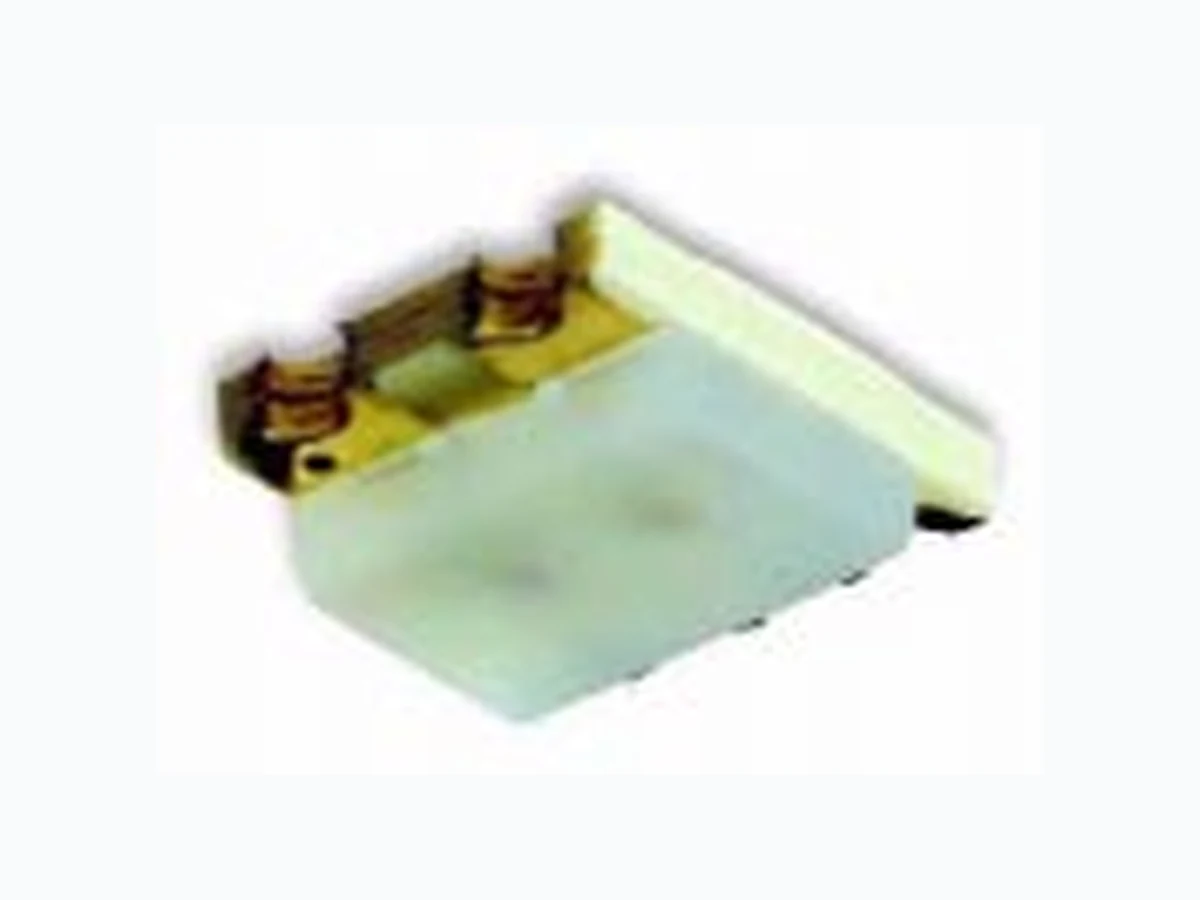
LSGF971 OSRAM
Document overview
- Manufacturer or author: Provided By www.digicamel.com(FREE DATASHEET DOWNLOAD SITE)
- PDF pages: 7
Technical content
Features
- colors: super-red (628 nm) and green (572 nm)
- color mixing is possible
- each chip can be controlled separately
- industry standard footprint
- suitable for all SMT assembly and IR soldering methods
- low profile
- available taped on reel (8 mm tape) Anwendungen
- Handy-Hinterleuchtung
- Einkopplung in Lichtleiter
- LCD-Hinterleuchtung
- Schalter-Hinterleuchtung
- Spielsachen
- Armbanduhren
- Taschenrechner
Applications
- hand phone back lighting
- coupling in any light pipe
- LCD back lighting
- switch back lighting
- toys
- watches
- pocket calculators
1) nur ein Chip betrieben one system only Typ Type Emissionsfarbe Color of Emission Farbe der Lichtaustritts- fläche Color of the Light Emitting Area Lichtstärke Luminous Intensity IF = 20 mA I V (mcd) Bestellnummer Ordering Code min. typ. LSG F971 super-red green colorless diffused 6.3 Q62703-Q4728 Bezeichnung Parameter Symbol Symbol Wert Value Einheit Unit Betriebstemperatur Operating temperature range Lagertemperatur Storage temperature range Sperrschichttemperatur Junction temperature Tj + 95 °C Durchlaßstrom Forward current IF 25 mA Stoßstrom Surge current tp = 10 µs, D = 0.1 IFM t.b.d. A Sperrspanung Reverse voltage VR 5V Verlustleistung Power dissipation Ptot 65 mW Wärmewiderstand 1) Sperrschicht / Umgebung Thermal resistance 1) Junction / air Rth JA 750 K/W
Kennwerte (TA = 25 °C) Characteristics Bezeichnung Parameter Symbol Symbol Werte Values Einheit Unit LS LG Wellenlänge des emittierten Lichtes (typ.) Wavelength at peak emission IF = 20 mA λpeak 642 570 nm Dominantwellenlänge (typ.) Dominant wavelength IF = 20 mA λdom 628 572 nm Spektrale Bandbreite (typ.) Spectral bandwidth IF = 20 mA Δλ 40 30 nm Abstrahlwinkel bei 50 % IV (Vollwinkel) Viewing angle at 50 % IV 2ϕ 160 160 Grad deg. Durchlaßspannung (typ.) Forward voltage (max.) IF = 20 mA VF VF 2.0 2.6 2.2 2.6 V V Sperrstrom (typ.) Reverse current (max.) VR = 5 V IR IR 0.01 0.01 µA µA Temperaturkoeffizient von λ dom (typ.) Temperature coefficient of λdom IF = 20 mA TC λdom 0.05 0.06 nm/K Temperaturkoeffizient von λpeak (typ.) Temperature coefficient of λpeak IF = 20 mA TC λpeak 0.13 0.10 nm/K Temperaturkoeffizient von VF (typ.) Temperature coefficient of VF IF = 20 mA TC VF – 1.7 – 1.4 mV/K Temperaturkoeffizient von IV (typ.) Temperature coefficient of IV IF = 20 mA
Relative spektrale Emission Irel = f (λ), TA = 25 °C, IF = 20 mA Relative spectral emission V(λ) = spektrale Augenempfindlichkeit standard eye response curve Abstrahlcharakteristik Irel = f (ϕ) Radiation characteristic OHL00553 400 100 Ιrel λ λV 450 500 550 600 650 700 green super-red nm 0.2 0.4 1.0 0.8 0.6 ϕ 1.0 0.8 0.6 0.4 50˚ 60˚ 70˚ 80˚ 90˚ 100˚
Durchlaßstrom IF = f (VF) Forward current TA = 25 °C Maximal zulässiger Durchlaßstrom Max. permissible forward current IF = f (TA) Relative Lichtstärke IV /IV(20 mA) = f (IF) Relative luminous intensity TA = 25 °C 10 -3 V OHL00643 IF FV mA 1.0 -210 -110 010 110 210 greensuper-red OHL00648 0 1002 0 4030 50 70 60 IF 25 mA 100 AT V V (20 mA) 10 -1 0 10 10 12 10mA 10 -2 OHL00647 FΙ 110 Ι Ι 10 -1 10 0 green super-red
Empfehlung Lötpaddesign Infrarot/Vapor-Phase Reflow-Lötung Recommended Pad Infrared Vapor-Phase Reflow-Soldering Empfohlenes Lötprofil nach CECC 00802 für Infrarot/Vapor-Phase Reflow-Lötung Recommended Soldering Profileacc. to CECC 00802 for Infrared Vapor-Phase Reflow-Soldering OHAP0662 1.5 2.0 1.5 1.0 1.0 0.4 OHLA0685 0:00 T t C min 100 150 200 250 0:30 1:00 1:30 2:00 2:30 3:00 3:30 4:00 4:30 5:00 5:30 2-3 K/s 2-3 K/s T = 183 ˚C = 70 st maxT = 245 ˚C
Gurtausführung / Polarität und Lage Verpackungseinheit 3000/Rolle ø180 mm Method of Taping / Polarity and OrientationPacking unit 3000/Reel ø180 mm Maßzeichnung (Maße in mm, Toleranz ± 0.1 mm, wenn nicht anders angegeben) Package Outlines (Dimensions in mm, tolerance ± 0.1 mm unless otherwise specified) OHA00664 Polarity 3.75 1.75 1.3 0.2 Processive Direction Cathode Mark ±0.05 ±0.1ø1.5 4 ±0.1 3.15 ±0.14 ±0.052 ±0.053.5 ±0.38 ±0.1 GEO06020 (2.7) (0.9) (1.6) LED die (0.6) ResinP.C. board Polarity (3.2) (0.5) (1.1) (2.0) (2.0) ø(0.6) Cathode mark Soldering terminal (1.4) (0.9) may flow in x, y direction) Soldering terminal (size: 0.9 x 0.5 LH R974 reversed on Polarity is