


 Download PDF
LS505 GENNUM
Document overview
- PDF pages: 5
Technical content
Page 1
FEATURES
- 72 dB typical gain
- 0.2 to 2.0 mA of transducer current adjustment
- 43 dB range of feedback volume control
- 1.0 to 1.6 V supply operating range
- Schottky diodes provide symmetrical peak clipping
- requires only 4 external parts for operation
STANDARD PACKAGING
- 8 pin MINIpac
- 8 pin MICROpac
- 8 pin PLID®
- 8 pin SLT
- Chip (56 x 55 mils)
VMIC VB 4 8
2.2k
+
I/P 6
-
100
RVC 5
7
GND
High Gain Class A Amplifier
with Peak Clipping
LS505 DATA SHEET
DESCRIPTION
The LS505 is a low voltage, monolithic integrated circuit amplifier comprised of an operational amplifier driving a single transistor Class A output stage with open collector. Also included are a pair of complementary Schottky diodes which provide the capability for symmetrical peak clipping in a feedback configuration.
An internal negative feedback loop ensures a stable operating point for the output stage over the designed operating voltage. This also permits trimming of the output current with the use of a single external resistor.
The input stage and microphone are biased by an internal 2.2 kΩ decoupling resistor to increase battery line signal rejection.
MPO 1
O/P 3
33k
200
2 RE
BLOCK DIAGRAM
All resistors in ohms, all capacitors in farads unless otherwise stated.
Revision Date: January 1996
Document No. 500 - 20 - 11
GENNUM CORPORATION P.O. Box 489, Stn A, Burlington, Ontario, Canada L7R 3Y3 tel. (905) 632-2996 fax: (905) 632-5946 Japan Branch: A-302, Miyamae Village, 2–10–42 Miyamae, Suginami–ku Tokyo 168, Japan tel. (03) 3334-7700 fax (03) 3247-8839
Page 2
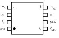
PIN CONNECTION
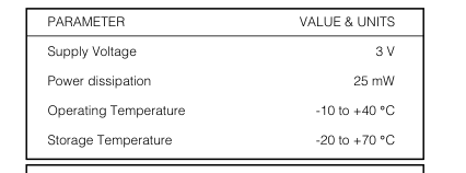
ABSOLUTE MAXIMUM RATINGS
ELECTRICAL CHARACTERISTICS
Conditions: Temperature 25 oC, Supply Voltage VB = 1.55 VDC
| PARAMETER | SYMBOL | CONDITION | MIN | TYP | MAX | UNITS |
|---|---|---|---|---|---|---|
| Gain | A CL | V = 0.707 VRMS O | 68 | 72 | 76 | dB |
| Temperature Coefficient of Gain | η A | - | 0.07 | - | o dB/ C | |
| Amplifier Current | I AMP | 180 | 210 | 280 | µA | |
| Temperature Coefficient of Current | η Ι | - | -0.002 | - | o mA/ C | |
| Transducer Current | I TRANS | 1.3 | 1.5 | 1.9 | mA | |
| Total Harmonic Distortion | THD | V = 0.707 VRMS O | - | 2 | 5 | % |
| Input Referred Noise | IRN | NFB 0.2 to 10 kHz at 12 dB/oct | - | 1.2 | 2.0 | µVRMS |
| Battery Resistance Stability | R = 22Ω B | - | - | 22 | Ω | |
| Volume Control Range | R = 100 to 100.1 kΩ S1 open VC | 36 | 43 | - | dB | |
| Input Impedance (Pin 6) | R IN | - | 27 | - | kΩ | |
| Frequency Response (-3 dB) | Low High | - - | 100 5K | - - | Hz Hz | |
| Maximum Output | S2 closed | 0.125 | 0.19 | 0.275 | VRMS | |
| Gain Dependence of RB | - | 0.16 | - | dB/Ω | ||
| Emitter Bias Voltage (Pin 2) | V RE | - | 42.5 | - | mV |
All switches and parameters remain as shown in test circuit unless stated in condition column
Page 3
RB = 4.7 VB = 1.5 VDC
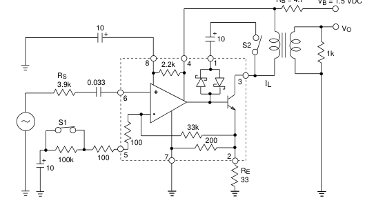
All resistors in ohms, all capacitors in µF unless otherwise stated
Fig. 1 Test Circuit
VMIC
INPUT
VOLUME
CONTROL
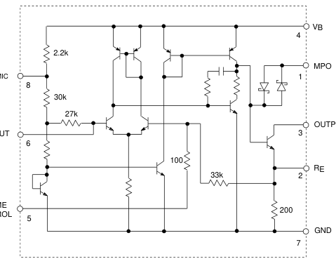
All resistors in ohms, all capacitors in farads unless otherwise stated U.S. Patent No. 4,034,306 - Patented in other countries
Fig. 2 Functional Schematic
Page 4
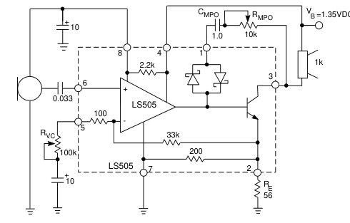
All resistors in ohms, all capacitors in farads unless otherwise stated
Fig. 3 Typical Hearing Aid Applications
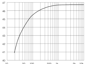
10 50 100
500 1k
5k 10k
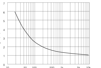
EXTERNAL RESISTANCE (Ω)
Fig. 4 Volume Control Range vs RE
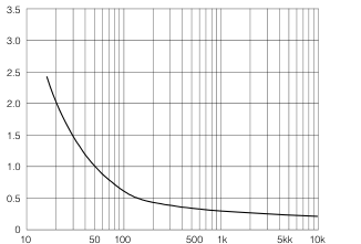
EXTERNAL RESISTANCE RE (Ω)
Fig. 6 Load Current vs External Resistance
RE Ω
Fig. 5 GM vs RE Ω
Ω
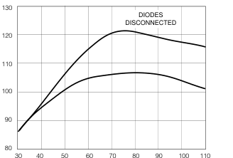
INPUT (dBSPL)
Fig. 7 I/O Characteristics
Page 5
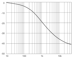
RVC (Ω)
Fig. 8 Relative Voltage Gain vs Volume Control Resistance
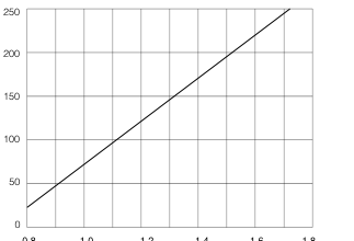
0.8 1.0 1.2 1.4 1.6 1.8
SUPPLY VOLTAGE (V)
Fig. 10 Amplifier Current vs Supply Voltage
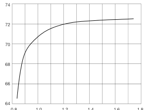
0.8 1.0 1.2 1.4 1.6 1.8 SUPPLY VOLTAGE (V)
Fig. 12 Gain vs Supply Voltage
REVISION NOTES Au bump removed
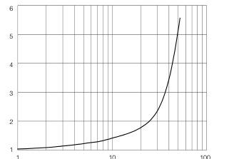
BATTERY RESISTANCE RB (Ω)
Fig. 9 Relative Voltage Gain vs Battery Resistance
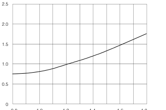
0.8 1.0 1.2 1.4 1.6 1.8 SUPPLY VOLTAGE (V)
Fig. 11 Load Current vs Supply Voltage
Gennum Corporation assumes no responsibility for the use of any circuits described herein and makes no representations that they are free from patent infringement.
© Copyright October 1977 Gennum Corporation. All rights reserved. Printed in Canada.