
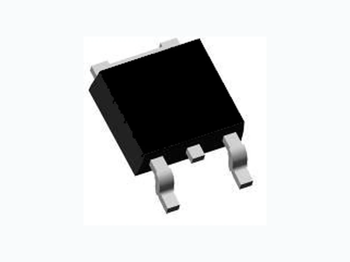
LM6035D LEIDITECH
Document overview
- Manufacturer or author: Provided By www.digicamel.com(FREE DATASHEET DOWNLOAD SITE)
- PDF pages: 6
Technical content
AGE MARKING AND ORDERING INFORMATION De vice Marking Device Device Package Reel Size Tape width Quantity LM6035D TO-252 - - - ABS OLUTE MAXIMUM RATINGS(TA=25℃unless otherwise noted) Parameter S ymbol Limit Unit Drain-S ource Voltage VDS -60 V Gate-Source Voltage VGS ±20 V ID(25℃) -26 A ID(70℃) -20 A Drain C urrent-Continuous@ Current-Pulsed (Note 1) IDM -60 A Maximum Po wer Dissipation PD 60 W Operatin g Junction and Storage Temperature Range TJ,TST G -55 T o 175 ℃ THER MAL CHARACTERISTICS T hermal Resistance,Junction-to-Ambient (Note 2) RθJA 25 ℃/W ELECTRI CAL CHARACTERISTICS (TA=25℃unless otherwise noted) Parameter S ymbol Condition Min Typ Max Unit OFF CH ARACTERISTICS Drain-S ource Breakdown Voltage BVDS S VGS=0 V ID=-2 50μA -60 V GENERAL
FEATURES
- V DS =- 60V ,ID = -26A RDS (ON) < 40mΩ @ VGS= -10V RDS (ON) < 55mΩ @ VGS= -4.5V
- High Power and current handing capability
- Lead free product is acquired
- Surface Mount Package DES CRIPTION T he SSFD6035 uses advanced trench technology to provide excellent RDS (ON) and l ow gate charge .This device is suitable for use as a load switch or in PWM applications. Application
- PW M applications
- Load switch
- Power management Enhancement Mode Fieid Effect Transistor P-Channel LM6035D Rev TO-252 Schematic diagram D G S D G S
V = -48V,V =0V -1 μA Zero Gate Voltage Drain Current IDS S DS GS Gate-Bod y Leakage Current I V =±20V,V =0V ±100 nA GSS GS DS ON CH ARACTERISTICS (Note 3) Gate T hreshold Voltage V V =VGS( th) DS GS,ID=-25 0μA -1 -1.8 -2.5 V V = -10V, IGS D= -20A 31 40 mΩ Drain-S ource On-State Resistance RDS (ON) V = -4.5V, IGS D=-20A 42 55 mΩ F orward Transconductance g V =-5V,IFS DS D= -20A 5 S DYN AMIC CHARACTERISTICS (Note4) Input Cap acitance C 3060 PF lss Output Cap acitance Coss 300 PF V = -30V,V Reverse Transfer Capacitance Crss DS GS=0V, F=1.0MHz 205 PF SWITCHING C HARACTERISTICS (Note 4) T urn-on Delay Time t 14 nS d( on) T urn-on Rise Time t 20 nS r T urn-Off Delay Time td( off) 40 nS V = -30V,V =-10V,R Turn-Off Fall Time tf DS GS GEN=3Ω ID=1 A 19 nS T otal Gate Charge Q 48 nC g Gate-Source C harge Qgs 11 nC V = -30V,I Gate-Drain Charge Qgd DS D= -20A,V =-10VGS 10 nC Bod y Diode Reverse Recovery Time T 40 nS rr IF= -20A, dI/dt=100A/µs Body Diode Reverse Recovery Charge Q 56 nC rr DR AIN-SOURCE DIODE CHARACTERISTICS Diod e Forward Voltage (Note 3) V V =0V,I =-1A -0.72 -1 V SD GS S NOTES: 1. R epetitive Rating: Pulse width limited by maximum junction temperature. 2. Surface Mounted on 1in2 F R4 Board, t ≤ 10 sec. 3. Pulse Test: Pulse Width ≤ 300μs, Duty Cycle ≤ 2%. 4. Guaranteed by design, not subject to production testing. LM6035D Rev
urrent (A) -Vgs Gate-Source V oltage (V) TJ-Junction T emperature(℃) Figure 7 T ransfer Characteristics Figure 8 Drain-Source On-Resistance Rdson On- Resistance(mΩ) C Cap acitance (pF) -Vgs Gate-Source V oltage (V) -Vds Drain-Source Voltage (V) Figure 10 Cap acitance vs Vds Figure 9 Rdson vs Vgs -Vgs Gate-Source V oltage (V) s- Reverse Drain Cu rrent (A) -I Qg Gate Ch arge (nC) -Vsd Source-Drain Voltage (V) Figure 1
1 Gate Charge Figure 12 Source- Drain Diode Forward
urrent (A) Vds Drain-Source V oltage (V) Figure
13 Safe Operation Area
Square Wave Pluse Duration(sec) Figure 14 Normalized Maximum Tra nsient Thermal Impedance ZthJ A No rmalized Transient Thermal Resistance LM6035D Rev
UNITS:mm NOTES: 1. D imensions are inclusive of plating 2. Package body sizes exclude mold flash and gate burrs. Mold flash at the non-lead sides should be less than 6 mils. 3. Dimension L is measured in gauge plane. 4. Controlling dimension is millimeter, converted inch dimensions are not necessarily exact. LM6035D Shanghai Leiditech Electronic Co.,Ltd Email: sale1@leiditech.com Tel : +86- 021 50828806 Fax : +86- 021 50477059 Rev