
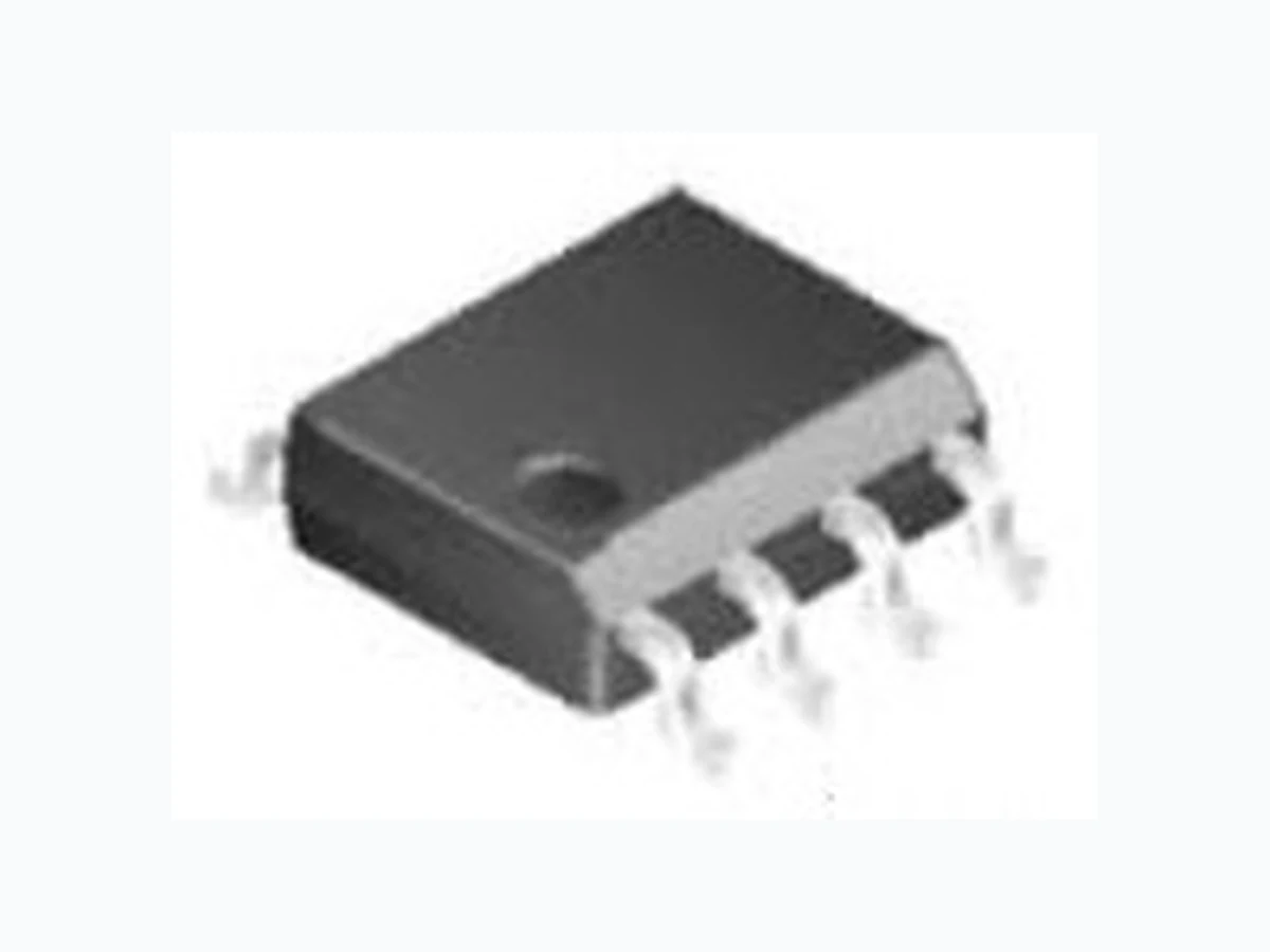
LM1503 LEIDITECH
Document overview
- Manufacturer or author: Provided By www.digicamel.com(FREE DATASHEET DOWNLOAD SITE)
- PDF pages: 6
Technical content
Features
ID (at VGS=10V) 13A RDS(ON) (atVGS=10V) 15mΩ(Max) RDS(ON) (atVGS=4.5V) 20mΩ(Max) AbsoluteMaximumRatings T A=25°C unlessotherwisenoted Parameter Symbol Maximum Units Drain-SourceVoltage VDS 30 V Gate-SourceVoltage VGS ±20 V DrainCurrent-Continuous TC=25°C ID A TC=100°C ID 8.5 A DrainCurrent – Pulsed IDM A MaximumPower Dissipation PD 2.1 W JunctionandStorage TemperatureRange TJ,TSTG -55To 150 ℃ Thermal Characteristics Parameter Symbol Typ Max Unit ThermalResistancejunction-case RθJc 7 ℃ /W ThermalResistanceunction-to-Ambient RθJA 62 ℃ /W G D S SOP8 G S S S D D DD LM1503 Enhancement Mode Power MOSFET N-Channel Rev : www.leiditech.com 01.06.2018 1/6
ElectricalCharacteristics(TJ=25 ℃ unlessotherwisenoted) Symbol Parameter Condition Min Typ Max Unit STATIC PARAMETERS BVDSS Drain-SourceBreakdown Voltage VGS=0VID=250μA 30 V IDSS ZeroGate VoltageDrainCurrent VDS=30V,VGS=0V 1 μA IGSS Gate-BodyLeakageCurrent VGS=±20V,VDS=0V ±100 nA VGS(th) Gate ThresholdVoltage VDS=VGS,ID=250μA 0.6 1.0 1.5 V RDS(ON) Drain-Source On-State Resistance VGS=10V, ID=10A 12 15 mΩ VGS=4.5V,ID=5A 14 20 mΩ DYNAMICPARAMETERS Clss Input Capacitance VDS=15V,VGS=0V, F=1.0MHz 620 pF Coss OutputCapacitance 85 pF Crss ReverseTransferCapacitance 60 pF SWITCHINGPARAMETERS td(on) Turn-on DelayTime VGS=10V VDS=15V RL=2.6Ω RGEN=3Ω 2.6 nS tr Turn-on RiseTime 8.5 nS td(off) Turn-Off DelayTime 18 nS tf Turn-Off FallTime 5 nS Qg Total GateCharge VDS=15V,ID=3A, VGS=4.5V 7.1 nC Qgs Gate-SourceCharge 1.4 nC Qgd Gate-DrainCharge 1.5 nC VSD DiodeForward Voltage VGS=0V,ISD=1A 0.72 1.3 V Rg Gateresistance VGS=0V,VDS=0V, F=1MHz 2 Ω Note: 1. RepetitiveRating:Pulsedwidth limitedbymaximumjunctiontemperature. 2. Thedata testedbypulsed,pulsewidth ≦ 300us,dutycycle ≦ 2%. 3. Essentiallyindependentof operatingtemperature. LM1503 Rev : www.leiditech.com 01.06.2018 2/6
TYPICAL ELECTRICAL AND THERMAL CHARACTERISTICS TC , Case Temperature (℃) Fig.1 Continuous Dr ain Current vs. TC TJ , Junction Temperature (℃) Fig.3 Normalized Vth vs. TJ I D , Continuous Drain Current (A) Normalized On Resistance (mΩ) TJ , Junction Temperature (℃) Fig.2 Normalized RDSON vs. TJ Normalized Gate Threshold V oltage (V) V GS Gate to Source Voltage (V) Qg , Gate Charge (nC) Fig.4 Gate Charge W aveform Normalized Thermal Response (R ΘJA I D , Continuous Drain Current (A) VDS , Drain to Source Voltage (V) Fig.6 Maximum Safe Operation Area Square Wave Pulse Duration (s) Fig.5 Normalized Transient Response LM1503 Rev : www.leiditech.com 01.06.2018 3/6
TYPICAL ELECTRICAL AND THERMAL CHARACTERISTICS T d(on) T r T on T d(off) T f T off V DS V GS 90% 10% I AS V GS
1 L x I
xEAS= BV DSS V DD BV DSS BV DSS DD Fig.8 EAS Waveform Fig.7 Switching Time Waveform LM1503 Rev : www.leiditech.com 01.06.2018 4/6
Gate Charge Test Circuit & Waveform VDC DUT Vdd Vgs Vds Vgs RL Rg Vgs Vds 10% 90% Resistive Switching Test Circuit & Waveforms t d(on) t r t on t d(off) t f t off Unclamped Inductive Switching (UIS) Test Circuit & Waveforms Ig Vgs VDC DUT L Vgs Vds IsdIsd Diode Recovery Test Circuit & Waveforms Vds - Vds + IF dI/dt IRM rr VddVdd Q = - Idt trr Vdd Vgs Id Vgs Rg DUT VDC L L Vgs Vds Id Vgs B BV VV Vd ds s I AR D DS SS S 2 2 E E A A R R = = 1 1/ /2 2 L LI I A AR R LM1503 Rev : www.leiditech.com 01.06.2018 5/6
Symbol Dim ensions In Millimeters Dimensions In Inches Min Max Min Max A 1.350 1.750 0.053 0.068 A1 0.100 0.250 0.004 0.009 A2 1.300 1.500 0.052 0.059 A3 0.600 0.700 0.024 0.027 b 0.390 0.480 0.016 0.018 c 0.210 0.260 0.009 0.010 D 4.700 5.100 0.186 0.200 E 5.800 6.200 0.229 0.244 E1 3.700 4.100 0.146 0.161 e 1.270(BSC) 0.050(BSC) h 0.250 0.500 0.010 0.019 L 0.500 0.800 0.019 0.031 L1 1.050(BSC) 0.041(BSC) θ 0° 8° 0° 8° SOP8 PACKAGE INFORMATION LM1503 Shanghai Leiditech Electronic Co.,Ltd Email: sale1@leiditech.com Tel : +86- 021 50828806 Fax : +86- 021 50477059 Rev : www.leiditech.com 01.06.2018 6/6