
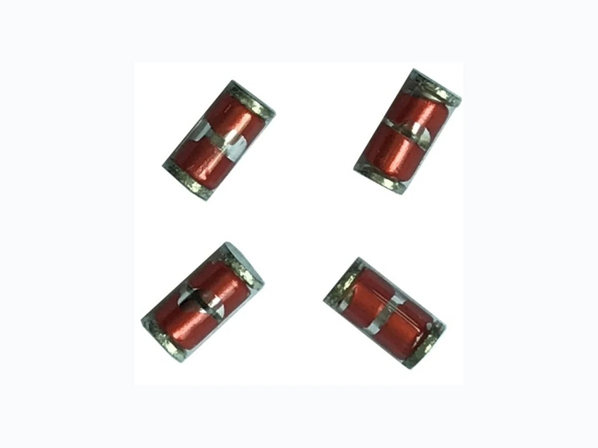
LM102 LEIDITECH
Document overview
- Manufacturer or author: Provided By www.digicamel.com(FREE DATASHEET DOWNLOAD SITE)
- PDF pages: 4
Technical content
Features
l RoHS compliant. l Bilateral symmetrical. l Less decay at on/off state. l Approximately zero leaking current before clamping voltage l High capability to withstand repeated lightning strikes. l Low electrode capacitance(≤1.0pF) and high isolation (≥100MΩ). l Temperature, humidity and lightness insensitive. l Working temperature range: : -45 ~ +85℃℃ l Storaging temperature range: -45℃ ~ +85℃
Applications
l Motor sparks eliminating l Relay switching spark absorbing l Data line pulse guarding l Telephone/Fax/Modem l High frequency signal transmitters/receivers l Satellite antenna l Radio amplifiers l Alarm systems l Cathode ray tubes in Monitors/ Television Viewing Systems Part Number Code M DC Spark– over voltage tolerance L 1 2 0 N:30% M:20% Brand Name 4 - 1 1 N Taping form Blank: Line M:SMD Surge Current Capacity 102:1KA DC Spark-over voltage(Vs) 14*101=140V LM102 Series Rev : www.leiditech.com 01.06.2018 1/4
Electrical Characteristics
Min. Insulation Resistance Max. Capacitance (1kHz-6Vmax. ) Surge Current Capacity Surge Life Test @8/20μs Vs Test Voltage IR Cj 8/20μs V V MΩ pF A M102-141N 140(126~210) 50 100 1 1000 100A 10 times LM102-181N 180±30% 50 100 1 1000 100A 10 times LM102-201M 200±20% 100 100 1 1000 100A 10 times LM102-301M 300±20% 100 100 1 1000 100A 10 times LM102-401M 400±20% 250 100 1 1000 100A 10 times LM102-501M 500±20% 250 100 1 1000 100A 10 times Test Methods And Results Test Item Test Method Specification DC Spark-over Voltage Vs(V) Add and measure the DC Voltage gradually Maxto get the discharge threshold voltage. The measuring current is 1mA/1 second max. It depands on each spec. Insulation Resistance Measure the insulation resistance of two end of leadwire under the specified DC voltage. 100MΩ min. Capacitance Cj(pF) Measure the Electrostatic Capacitance under the test condition of 1KHz,DC 6V(max). 1pF max. Life(JSE) Apply a standard impulse voltage (8X20μsec)of 100A for 5 times with intervals of 30 sec., and then change the polarity of the surge and apply a impulse again. Then measure DC spark-over voltage, IR & Capacitance. DC spark-over voltage JSE:∣△ Vs/Vs ∣ ≤30% Life(JSE) Apply 10 KV voltage charged in 1500pF condenser and apply the current to the specimen,200 times at 10 seconds of intervals Insulation Resistance & Capacitance to meet the specified value. Appearance: No cracks or failures. Cold Resistance Measurement after -40℃ /1000 HRS & normal temperature/2 HRS. Features are conformed to rated spec. Heat Resistance Measurement after 125℃ /1000 HRS & normal temperature/2 HRS. Humidity Resistance Measurement after humidity 90~95 ℃ (45 ℃ ) /1000 HRS & normal temperature/2 HRS. Temperature Cycle 10 times repetition of cycle -40 ℃ /30min →normal, temp/2 min →125℃ /30min, measurement after normal temp/2 HRS. Pull Strength Apply 0.5kg load for 10sec. Lead shall not pull out to snap. Flexural Strength Bend lead wire at the point of 2mm from body under 0.25 load and back to its original point. Repeat 1 time. LM102 Series L Rev : www.leiditech.com 01.06.2018 2/4
Recommended Soldering Conditions Flow Soldering Conditions Hand Soldering Solder iron temperature: 350±5℃ Heating time: 3 seconds max. General attention to soldering 1.High soldering temperatures and long soldering times can cause leaching of the termination, decrease in adherence strength, and the change of characteristic may occur. 2.For soldering, please refer to the soldering curves above. However, please keep exposures to temperatures exceeding 200℃ to fewer than 50 seconds. 3.Please use a mild flux (containing less than 0.2wt% CI). Also, if the flux is water soluble, be sure to wash thoroughly to remove any residue from the underside of components that could affect resistance. 1) Time shown in the above figures is measured from the point when chip surface reaches temperature. 2) Temperature difference in high temperature part should be within 110℃ 3) After soldering, do not force cool, allow the parts to cool gradually. Cleaning When using ultrasonic cleaning, the board may resonate if the output power is too high. Since this vibration can cause cracking or a decrease in the adherence of the termination, we recommend that you use the conditions below. Frequency: 40kHz max. Output power: 20W/liter Cleaning time: 5 minutes max. Dimensions DIM Millimeters Inches 250 200 150 100 150~180℃ Air Priheat 260℃ T Soldering Cooling 3~4 sec 60~120 sec Temperature() LM102 Series Rev : www.leiditech.com 01.06.2018 3/4
Taping and Reel Specifications Symbol Millimeters Inches D1 178.0 7.007 D0 13.0 0.512 W1 15.0 0.591 Quantity:1500PCS / inner box LM102 Series Shanghai Leiditech Electronic Co.,Ltd Email: sale1@leiditech.com Tel : +86- 021 50828806 Fax : +86- 021 50477059 Rev : www.leiditech.com 01.06.2018 4/4