
LM0804 LEIDITECH
Document overview
- Manufacturer or author: Provided By www.digicamel.com(FREE DATASHEET DOWNLOAD SITE)
- PDF pages: 6
Technical content
Features
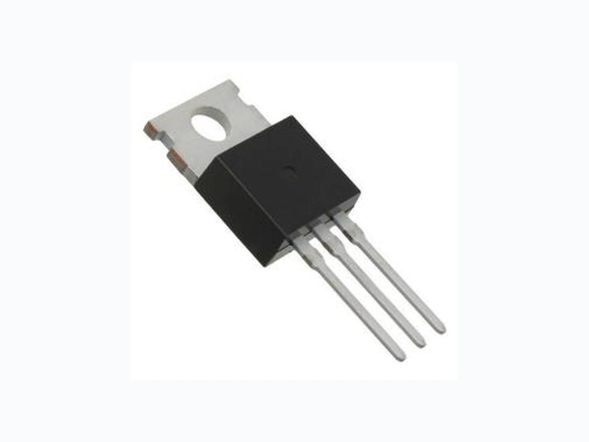
ID (at VGS=10V) 140A RDS(ON) (atVGS=10V) 3.7mΩ(Typ) Absolute Maximum Ratings TA=25°C unless otherwise noted Parameter Symbol Maximum Units Drain-SourceVoltage VDS 80 V Gate-SourceVoltage VGS +20/-12 V DrainCurrent-Continuous TC=25°C ID 140 A TC=100°C ID A MaximumPower Dissipation PD 150 W Single pulseavalancheenergy(1) EAS 540 mJ JunctionandStorage TemperatureRange TJ,TSTG -55To 150 ℃ Thermal Characteristics Parameter Symbol Typ Max Unit ThermalResistancejunction-case RθJc 1.1 ℃ /W ThermalResistanceunction-to-Ambient RθJA 62 ℃ /W D G S G D S TO220 TO263 G D S LM0804 Super Trench Power MOSFET N-Channel Rev : www.leiditech.com 01.06.2018 1/6
Electrical Characteristics (TJ=25℃ unless otherwise noted) Symbol Parameter Condition Min Typ Max Unit STATIC PARAMETERS BVDSS Drain-SourceBreakdown Voltage VGS=0VID=250μA 80 V IDSS ZeroGate VoltageDrainCurrent VDS=80V,VGS=0V 1 μA IGSS Gate-BodyLeakageCurrent VGS=20V,VDS=0V 100 nA VGS(th) Gate ThresholdVoltage VDS=VGS,ID=250μA 2.0 3.0 4.0 V RDS(ON) Drain-Source On-State Resistance VGS=10V, ID=20A 3.7 4.4 mΩ DYNAMIC PARAMETERS Clss Input Capacitance VDS=30V,VGS=0V, F=1.0MHz 5500 pF Coss OutputCapacitance 970 pF Crss ReverseTransferCapacitance pF SWITCHING PARAMETERS td(on) Turn-on DelayTime VDD=40V,ID=1A, VGS=10V, RG=6Ω 22 nS tr Turn-on RiseTime 16 nS td(off) Turn-Off DelayTime 40 nS tf Turn-Off FallTime nS Qg Total GateCharge VDS=40V,ID=10A, VGS=10V nC Qgs Gate-SourceCharge nC Qgd Gate-DrainCharge nC VSD Diode Forward Voltage VGS=0V,ISD=10A 0.72 1.2 V Rg Gate resistance VGS=0V,VDS=0V, F=1MHz 1.5 Ω Note: 1. Repetitive Rating : Pulsed width limited by maximum junction temperature. 2. VDD=25V,VGS=10V,L=0.1mH,IAS=95A., Starting TJ=25℃ 3. The data tested by pulsed , pulse width ≦ 300us , duty cycle ≦ 2%. 4. Essentially independent of operating temperature. LM0804 Rev : www.leiditech.com 01.06.2018 2/6
TYPICAL ELECTRICAL AND THERMAL CHARACTERISTICS I D , Continuous Drain Current (A) TC , Case Temperature (℃) Fig.1 Continuous Drain Current vs. TC T J , Junction Temperature ( ) Fig.3 Normalized Vth vs. T J Normalized Gate Threshold V oltage (V) Qg , Gate Charge (nC) Fig.4 Gate Charge Characteristics VGS , Gate to Source V oltage (V) Square Wave Pulse Duration (s) Fig.5 Normalized Transient Impedance V DS , Drain to Source Voltage (V) Fig.6 Maximum Safe Operation Area Normalized Thermal Response (RθJC) ID , Drain Current (A) T J , Junction Temperature ( ) Fig.2 Normalized RDSON vs. T J Normalized On Resistance (mΩ ) LM0804 Rev : www.leiditech.com 01.06.2018 3/6
TYPICAL ELECTRICAL AND THERMAL CHARACTERISTICS Fig.7 Switching Time Waveform Fig.8 Gate Charge Waveform LM0804 Rev : www.leiditech.com 01.06.2018 4/6
Symbol Dimensions In Millimeters Dimensions In Inches MAX MIN MAX MIN A 10.300 9.700 0.406 0.382 A1 8.840 8.440 0.348 0.332 A2 1.250 1.050 0.049 0.041 A3 5.300 5.100 0.209 0.201 B 16.200 15.400 0.638 0.606 C 4.680 4.280 0.184 0.169 C1 1.500 1.100 0.059 0.043 D 1.000 0.600 0.039 0.024 E 3.800 3.400 0.150 0.134 G 9.300 8.700 0.366 0.343 H 0.600 0.400 0.024 0.016 K 2.700 2.100 0.106 0.083 L 13.600 12.800 0.535 0.504 M 1.500 1.100 0.059 0.043 N 2.590 2.490 0.102 0.098 T W0.35 W0.014 TO220 PACKAGE INFORMATION LM0804 Rev : www.leiditech.com 01.06.2018 5/6
Shanghai Leiditech Electronic Co.,Ltd Email: sale1@leiditech.com Tel : +86- 021 50828806 Fax : +86- 021 50477059 Rev : www.leiditech.com 01.06.2018 6/6