

 Download PDF
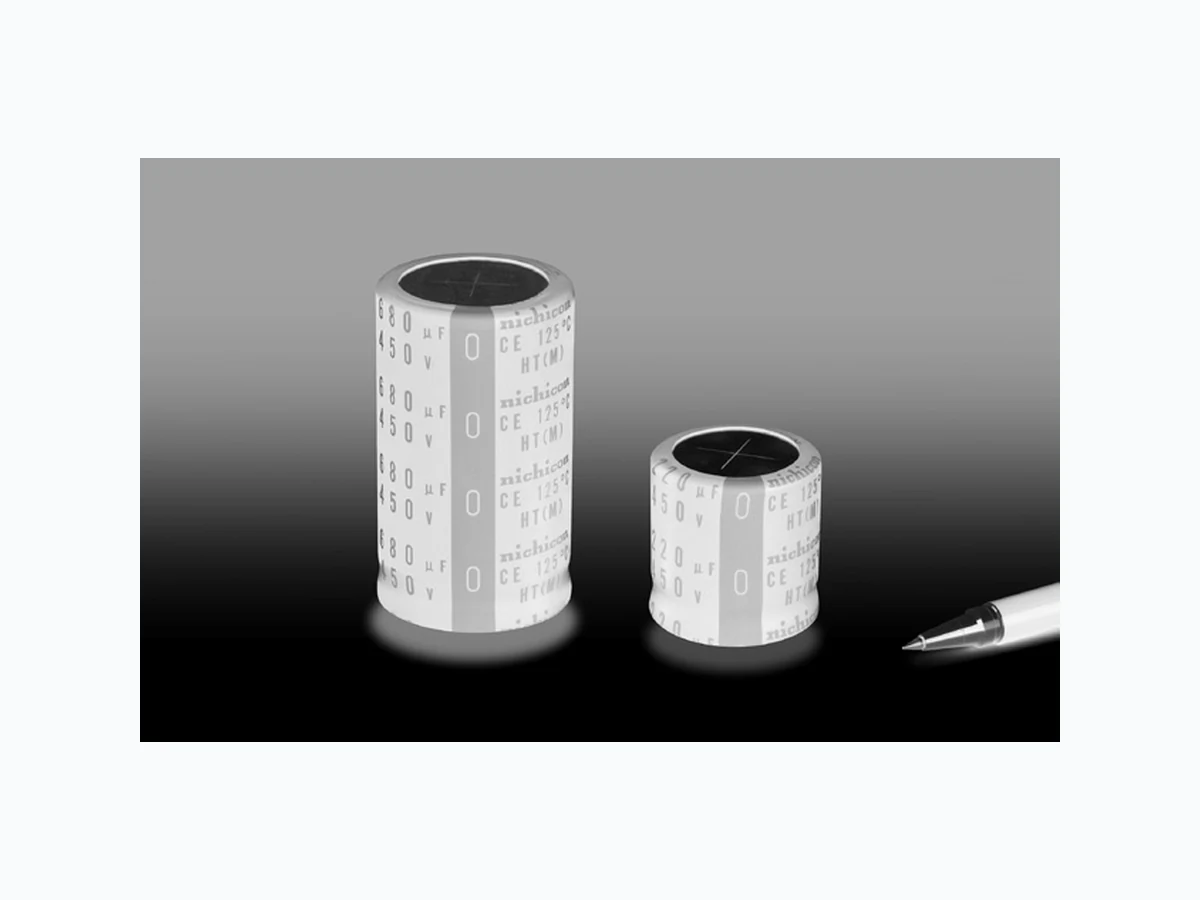
LHT NICHICON
Document overview
- PDF pages: 1
Technical content
Page 1
ALUMINUM ELECTROLYTIC CAPACITORS
LHT
Snap-in Terminal Type, 125°C Wide Temperature Range
Wide temperature range of LGN.
LGN
Contributing to high temperature support of equipment.
Compliant of the RoHS directive (2011/65/EU,(EU)2015/863).
wide temperature range
LHT
Specifications
| Item | Performance Characteristics |
| Category Temperature Range | – 40 to +125°C |
| Rated Voltage Range | 450V |
| Rated Capacitance Range | 220 to 680µF |
| Capacitance Tolerance | ±203% C aVt 120Hz, 20°C |
| Leakage Current | I 3 C V (µA) (After 5 minutes' application of rated voltage at 20°C) [C : Rated Capacitance (µF) V : Voltage (V)] |
| Tangent of loss angle (tan δ) | 0.32 0mCVax. 120Hz at 20°C |
| Stability at Low Temperature | Impedance ratio Z(–25°C) / Z(+20°C) 8 (120Hz) |
| Endurance | The specifications listed at right shall be met when the Capacitance change Within ± 20% of the initial capacitance value capacitors are restored to 20°C after D.C. bias plus rated ripple current is applied for 3000 hours at 125°C, the tan δ 200% or less than the initial specified value peak voltage shall not exceed the rated voltage. Leakage current Less than or equal to the initial specified value |
| Shelf Life | After storing the capacitors under no load at 125°C for Capacitance change Within ± 15% of the initial capacitance value 1000 hours and then performing voltage treatment based tan δ 150% or less than the initial specified value on JIS C 5101-4 clause 4.1 at 20°C, they shall meet the requirements listed at right. Leakage current Less than or equal to the initial specified value |
| Marking | Printed with white color letter on black sleeve. |
Drawing
Polarity bar
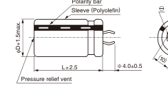
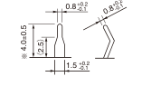
2×φ2±0.1
(Terminal dimensions)
(PC board hole dimensions)
Other terminations available upon request. Please refer to the Guidelines for Aluminum Electrolytic Capacitors.
| Capacitance change | Within ± 20% of the initial capacitance value |
| tan δ | 200% or less than the initial specified value |
| Leakage current | Less than or equal to the initial specified value |
| Capacitance change | Within ± 15% of the initial capacitance value |
| tan δ | 150% or less than the initial specified value |
| Leakage current | Less than or equal to the initial specified value |
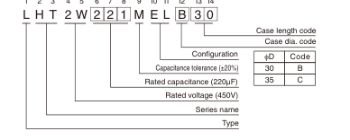
Type numbering system (Example : 450V 220µF)
1 2 3 4 5 6 7 8 9 10 11 12 13 14
Dimensions
| 450V (2W) | ||||
| Cap. (µF) | Size φD × L(mm) | Rated ripple (mArms) | Leakage Current (mA) | Code |
| 220 | 30 × 30 | 1120 | 0.94 | LHT2W221MELB30 |
| 270 | 30 × 35 | 1270 | 1.04 | LHT2W271MELB35 |
| 35 × 30 | 1340 | 1.04 | LHT2W271MELC30 | |
| 330 | 30 × 45 | 1480 | 1.15 | LHT2W331MELB45 |
| 35 × 35 | 1510 | 1.15 | LHT2W331MELC35 | |
| 390 | 30 × 50 | 1640 | 1.25 | LHT2W391MELB50 |
| 35 × 40 | 1700 | 1.25 | LHT2W391MELC40 | |
| 470 | 30 × 55 | 1840 | 1.37 | LHT2W471MELB55 |
| 35 × 45 | 1910 | 1.37 | LHT2W471MELC45 | |
| 560 | 35 × 50 | 2130 | 1.50 | LHT2W561MELC50 |
| 680 | 35 × 60 | 2430 | 1.65 | LHT2W681MELC60 |
Rated ripple current (mArms) at 125°C 120Hz
Frequency coefficient of rated ripple current
| Frequency (Hz) | 50 | 60 | 120 | 300 | 1 k | 10k | 50k or more |
| Coefficient | 0.77 | 0.82 | 1.00 | 1.16 | 1.30 | 1.41 | 1.43 |