
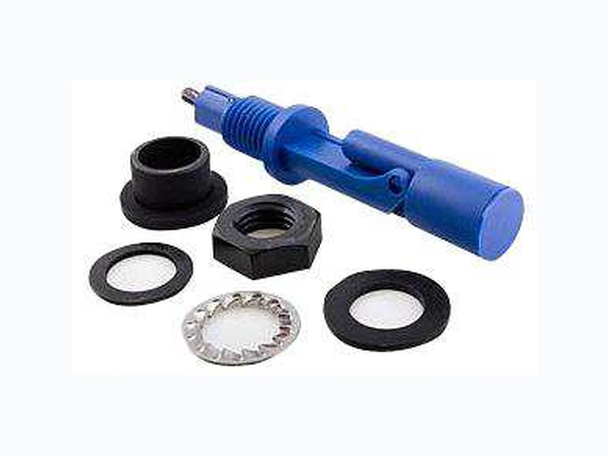

 Download PDF
LDS TEC
Document overview
- PDF pages: 4
Technical content
Page 1
te.com
HORIZONTAL SHORT-SWING
LIQUID LEVEL SENSORS
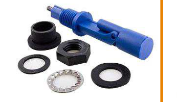
High- or low-level switching
N.O./N.C. SPST output
Mounted on the side wall of a tank
Certified reed switch (UL component listed)
Body and float made from glass filled nylon 6.6
The LDS series of point liquid level switches demonstrates a high degree of reliability due to the use of non-reactive wetted
Features
components and a unique reed switch designed specifically for level
Voltage rating up to 250VAC
sensing applications. The sensor utilizes a moving float with an embedded magnet to activate a reed switch located in the sensor
Current rating up to 1.0 amp
body. As the liquid level raises the float, it moves a magnet into
Compact design and low profile
close proximity of the reed switch and actuates it to give an open
Optional cable lengths
contact or closed contact switch indication.
Includes mounting hardware
The reliability of this sensor results from a very simple operating
Full and/or empty detection
principle, a single moving part, media compatible wetted materials, and a unique reed switch design that has a UL recognized component certification.
Applications
The sensor mounts into the side wall of a liquid storage tank using
Water and fuel storage tanks
an M16 x 2.0 threaded fitting. The M16 mount is available in an
Pump on/off controls
internal or external configuration. The output is a simple N.O. or N.C.
Marine bilge and ballast tanks
SPST reed switch that utilizes Ruthenium contact points for reliability. Changing from a N.O. output to a N.C. output is done by
Flood detection and prevention
rotating the switch 180° in the mounting hole. This change can be
Coolant level indication
done in the field. Electrical outputs are a single pair of wires with
Livestock watering tanks
PVC insulation and optional lengths of 0.5 m or 2.0 m.
Irrigation systems Water treatment plants Waste water tanks Chemical storage and processing
CLICK HERE ›
CONNECT WITH A SPECIALIST
Page 1
Page 2
Absolute Maximum Ratings (1)
| Parameter | Min | Max | Units | Notes/Conditions |
|---|---|---|---|---|
| DC contact voltage (SPST) | 200 | V | Do not exceed 70W | |
| DC contact current (SPST) | 1.0 | A | ||
| RMS contact voltage (SPST) | 250 | V | ||
| RMS contact current (SPST) | 1.0 | A | ||
| Storage and operating temperature | -30 | 105 | °C | |
| Fitting pressure | -1.0 | 4.7 | Bar | Internal tank pressure |
| Tank wall thickness (Internal mount) | 1.0 | 10 | mm | |
| Tank wall thickness(External mount) | 1.0 | 4.0 | mm |
(1) Maximum limits the device will withstand without damage
Product Specifications
| Parameter | Details & Options |
|---|---|
| Mounting Orientation | Side entry |
| Fitting | M16 x 2.0 Internal or External |
| Switch Operation | N.C. when float is horizontal |
| Contact Forms | Form A (SPST) |
| Contact Material | Ruthenium |
| Contact resistance (max) | 140 mΩ |
| Housing and Float Material | Glass filled nylon 6.6 (better for oil, fuel, non-ionic liquids) Glass filled Polypropylene (better for water and aqueous solutions) |
| Cable Description | 18 AWG 32/0.2mm PVC insulated, UL/CSA/BS6361 |
| Shock | ±50g 11ms half sign duration |
| Vibration | ±35g 0 – 500Hz |
| Ambient Humidity | 0 – 95% RH (non-condensing) |
| Ingress protection | IP68 (wetted surfaces) IP65 (non-wetted surfaces) |
| Approvals & Certifications | UL file E98428 |
Page 2
Page 3
Outline Dimensions

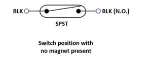
Schematic
Mounting Orientations

| Condition | Switch (SPST) |
|---|---|
| No liquid | Open |
| Liquid | Closed |
| Condition | Switch (SPST) |
|---|---|
| No liquid | Closed |
| Liquid | Open |
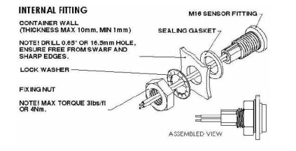
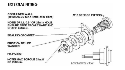
Mounting Detail & Hardware
Page 3
Page 4
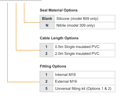
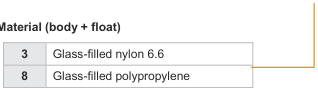
Ordering Information
Model Number
LDS __ __ __ - __ __ __

CLICK HERE ›
CONNECT WITH A SPECIALIST
NORTH AMERICA
EUROPE
ASIA
Tel +1 800 522 6752
Tel +31 73 624 6999
Tel +86 0400 820 6015
te.com/sensors
TE Connectivity, TE, TE Connectivity (logo) and Every Connection Counts are trademarks. All other logos, products and/or company names referred to herein might be trademarks of their respective owners
The information given herein, including drawings, illustrations and schematics which are intended for illustration purposes only, is believed to be reliable. However, TE Connectivity makes no warranties as to its accuracy or completeness and disclaims any liability in connection with its use. TE Connectivity‘s obligations shall only be as set forth in TE Connectivity‘s Standard Terms and Conditions of Sale for this product and in no case will TE Connectivity be liable for any incidental, indirect or consequential damages arising out of the sale, resale, use or misuse of the product. Users of TE Connectivity products should make their own evaluation to determine
the suitability of each such product for the specific application.
© 2020 TE Connectivity Corporation. All Rights Reserved.
Page 4