


 Download PDF
LDQ2D271MERY NICHICON
Document overview
- PDF pages: 1
Technical content
Page 1
ALUMINUM ELECTROLYTIC CAPACITORS
DQ series
Horizontal Mounting Type, Wide Temperature Range
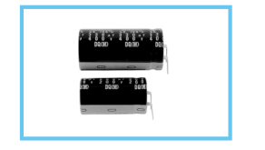
Horizontal mounting version for φ20 ,φ22 and φ25.
DQ
Suited for use in flat electronic devices where height space is limited.
Adapted to the RoHS directive (2002/95/EC).
High Temperature
DM
Specifications
Performance Characteristics
Item Category Temperature Range
– 40 ~ +105°C (200V) , – 25~+105°C (400V)
Rated Voltage Range
200 • 400V
Rated Capacitance Range
68 ~ 1200µF ± 20% at 120Hz, 20°C
Capacitance Tolerance
(µA) (After 5 minutes' application of rated voltage) [C : Rated Capacitance (µF) V : Voltage (V)] 3 CV
Leakage Current
I
Measurement frequency : 120Hz, Temperature : 20°C 200
400
Rated voltage (V)
tan δ
0.15
0.15
tan δ (MAX.)
Measurement frequency : 120Hz
| Rated voltage (V) | 200 | 400 | |
| Impedance ratio ZT/Z20(MAX.) | Z – 25°C/Z+20°C | 3 | 8 |
| Z – 40°C/Z+20°C | 12 | — | |
Stability at Low Temperature
After an application of DC voltage(in the range of rated DC voltage even after over-lapping the specified ripple current)
Endurance
for 2000 hours at 105°C, capacitors meet the characteristic requirements listed at right.
After storing the capacitors under no load at 105°C for 1000 hours, and after performing voltage treatment based
Shelf Life
on JIS C 5101-4 clause 4.1 at 20°C, they will meet the requirements listed at right. Printed with white color letter on black sleeve.
Marking
Drawing
L±2 3.5±1
Sleeve (P.E.T.)
0.6
Pressure relief vent
8.0±2
2.0
P ±1
φ20 : P=7.5 φ22, φ25 : P=8.5
Dimensions
200V (2D)
V(Code)
20
22
φD
Cap.(µF)
680 68 820 82 101 100 121 120 151 150 181 180 221 220 271 270
20× 30 1.10
331 330
20× 35 1.20
391 390
20× 40 1.31
471 470
20× 45 1.45 22× 35 1.45
561 560
20× 50 1.58 22× 40 1.60 25× 35
681 680
22× 45 1.78 25× 40
821 820
22× 60 2.04 25× 45
102 1000
25× 50
122 1200
25× 60
Other rating also available on request.
Frequency coefficient of rated ripple current
| Capacitance change | Within ±20% of initial value |
| tan δ | 200% or less of initial specified value |
| Leakage current | Initial specified value or less |
| Capacitance change | Within ±15% of initial value |
| tan δ | 150% or less of initial specified value |
| Leakage current | Initial specified value or less |
Type numbering system (Example : 200V 470µF)
1 2 3 4 5 6 7 8 9 10 11 12 13 14
L D Q 2 D 4 7 1 M E R Z G A
Lead wire configurationt
( HA : Right side from the front
)
GA : Left side from the front
Case dia.code φD Code
Configuration
20 Y
Capacitance tolerance(±20%)
22 Z
Rated Capacitance(470µF)
25 A
Rated voltage(200V) Series name Type
400V (2G)
25
20
22
25
20× 30 0.56 20× 30 0.64 20× 35 0.70 20× 40 0.75 22× 35 0.75
20× 45 0.83 22× 40 0.88
0.95
20× 50 0.95 22× 45 0.95 25× 35 1.10
22× 50 1.10 25× 40 1.22
22× 60 1.22 25× 45 1.44 25× 50
1.60 1.78 2.04
Rated
Case size
2.30
φ D ×L (mm) ripple
2.65
Rated Ripple (Arms) at 105°C, 120Hz
| Frequency (Hz) | 50 | 60 | 120 | 300 | 1k | 10k | 50k~ | |
| Coeff. | 200V | 0.81 | 0.85 | 1.00 | 1.17 | 1.32 | 1.45 | 1.50 |
| 400V | 0.77 | 0.82 | 1.00 | 1.16 | 1.30 | 1.41 | 1.43 | |