Download PDF
LCMC AVX
Document overview
- PDF pages: 13
Technical content
Page 1
Multi-Layer Ceramic Chip Inductors
LCMC Series
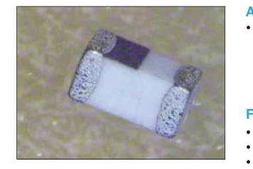
APPLICATIONS
- High Frequency Applications:
– Mobile Communications – WLAN
– PHS
– EMI Counter measure in High Frequency Circuits – Computer Communication
FEATURES
- For high frequency applications
- Standard EIA sizes 0201 (0603), 0402 (1005), 0603 (1608)
- Lead-free RoHS compliant parts
- Tight tolerance in physical dimensions
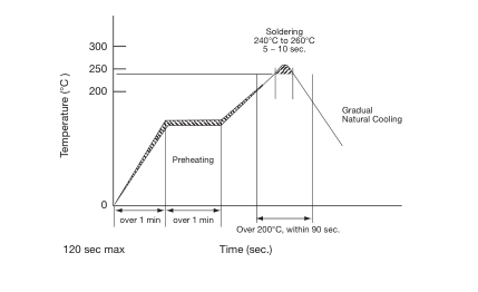
- Surface mounting applicability (Supports reflow soldering condition)
- Tight Inductance Tolerance, Excellent Q and Guaranteed SRF range
- High product quality and outstanding reliability. (Ceramic integrated structure)
- Operating temperature -55ºC to +125ºC
HOW TO ORDER
LC
MC
0402
101
G
T
A
R
K
Family
Series
Size
Inductance
Style Termination
Special Packaging
Tolerance
LC = Chip Inductor MC = Multi-Layer
0201
3N9 = 3.9nH
G = Standard T = Sn Plating A = Standard R = 7" Reel
G = 2% 0402
39N = 39nH H = 3% 0603
R39 = 390nH J = 5% K = 10% B = 0.1nH C = 0.2nH S = 0.3nH
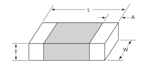
DIMENSIONS
mm (inches)
| Size | L | W | T | A | |
| Min | Max | ||||
| 0201 | 0.60 ± 0.03 (0.024 ± 0.001) | 0.30 ± 0.03 (0.012 ± 0.001) | 0.30 ± 0.03 (0.012 ± 0.001) | 0.10 (0.004) | 0.20 (0.008) |
| 0402 | 1.00 ± 0.10 (0.040 ± 0.004) | 0.50 ± 0.10 (0.020 ± 0.004) | 0.50 ± 0.10 (0.020 ± 0.004) | 0.10 (0.004) | 0.30 (0.012) |
| 0603 | 1.60 ± 0.15 (0.063 ± 0.006) | 0.80 ± 0.15 (0.031 ± 0.006) | 0.80 ± 0.15 (0.031 ± 0.006) | 0.20 (0.008) | 0.60 (0.024) |
AVAILABLE INDUCTANCE VALUE AND TOLERANCE
| Size Code | Available Inductance | Inductance Ranges | Standard Tolerance | Tolerance available upon request |
| LCMC0201 | 0.3nH - 100nH | 0.3nH - 4.2nH | S=±0.3nH | B=±0.1nH, C=±0.2nH |
| 4.3nH - 6.2nH | B=±0.1nH, H=±3% | |||
| 6.8nH - 27nH | J=±5% | H=±3% | ||
| 33nH - 100nH | J=±5% | – | ||
| LCMC0402 | 0.6nH - 270nH | 0.6 nH - 6.2 nH | S= ±0.3 nH | B= ±0.1 nH , C= ±0.2 nH |
| 6.8 nH - 82 nH | J= ±5% | G= ±2%, H=±3% | ||
| 100 nH - 270 nH | J= ±5% | – | ||
| LCMC0603 | 1.0 nH - 470 nH | 1.0 nH - 5.6 nH | S= ±0.3 nH | B= ±0.1 nH, C= ±0.2 nH |
| 6.8 nH - 470 nH | J= ±5% | G= ±2% |
Page 2
LCMC Series
ELECTRICAL CHARACTERISTICS
0201
| Ordering Code | Inductance (nH) | Available Tolerance | Q Min. | L, Q Measuring Frequency (MHz) | Self- Resonance Frequency (MHz) | DC Resistance (Ω) | Rated Current (mA) Max. | Packing Amount of 7" Reel Pcs | ||
|---|---|---|---|---|---|---|---|---|---|---|
| Min. | Typ. | Max. | Typ. | |||||||
| 0N3 | 0.3 | ±0.3nH, ±0.2nH, ±0.1nH | 4 | 100 | 10,000 | >13000 | 0.07 | 0.03 | 250 | 15000 |
| 0N4 | 0.4 | ±0.3nH, ±0.2nH, ±0.1nH | 4 | 100 | 10,000 | >13000 | 0.07 | 0.04 | 250 | |
| 0N5 | 0.5 | ±0.3nH, ±0.2nH, ±0.1nH | 4 | 100 | 10,000 | >13000 | 0.08 | 0.05 | 250 | |
| 0N6 | 0.6 | ±0.3nH, ±0.2nH, ±0.1nH | 4 | 100 | 10,000 | >13000 | 0.08 | 0.05 | 250 | |
| 0N7 | 0.7 | ±0.3nH, ±0.2nH, ±0.1nH | 4 | 100 | 10,000 | >13000 | 0.09 | 0.06 | 250 | |
| 0N8 | 0.8 | ±0.3nH, ±0.2nH, ±0.1nH | 4 | 100 | 10,000 | >13000 | 0.10 | 0.07 | 250 | |
| 0N9 | 0.9 | ±0.3nH, ±0.2nH, ±0.1nH | 4 | 100 | 10,000 | >13000 | 0.10 | 0.07 | 250 | |
| 1N0 | 1.0 | ±0.3nH, ±0.2nH, ±0.1nH | 4 | 100 | 10,000 | >13000 | 0.14 | 0.09 | 250 | |
| 1N1 | 1.1 | ±0.3nH, ±0.2nH, ±0.1nH | 4 | 100 | 10,000 | >13000 | 0.14 | 0.09 | 250 | |
| 1N2 | 1.2 | ±0.3nH, ±0.2nH, ±0.1nH | 4 | 100 | 10,000 | >13000 | 0.14 | 0.09 | 250 | |
| 1N3 | 1.3 | ±0.3nH, ±0.2nH, ±0.1nH | 4 | 100 | 10,000 | >13000 | 0.14 | 0.10 | 250 | |
| 1N5 | 1.5 | ±0.3nH, ±0.2nH, ±0.1nH | 4 | 100 | 10,000 | >13000 | 0.18 | 0.10 | 230 | |
| 1N6 | 1.6 | ±0.3nH, ±0.2nH, ±0.1nH | 4 | 100 | 10,000 | >13000 | 0.18 | 0.12 | 230 | |
| 1N8 | 1.8 | ±0.3nH, ±0.2nH, ±0.1nH | 4 | 100 | 10,000 | >13000 | 0.19 | 0.13 | 200 | |
| 2N0 | 2.0 | ±0.3nH, ±0.2nH, ±0.1nH | 4 | 100 | 8,800 | >13000 | 0.20 | 0.14 | 200 | |
| 2N1 | 2.1 | ±0.3nH, ±0.2nH, ±0.1nH | 4 | 100 | 8,800 | >13000 | 0.20 | 0.15 | 200 | |
| 2N2 | 2.2 | ±0.3nH, ±0.2nH, ±0.1nH | 4 | 100 | 8,800 | >13000 | 0.22 | 0.15 | 200 | |
| 2N4 | 2.4 | ±0.3nH, ±0.2nH, ±0.1nH | 4 | 100 | 8,300 | 11,700 | 0.24 | 0.15 | 200 | |
| 2N7 | 2.7 | ±0.3nH, ±0.2nH, ±0.1nH | 5 | 100 | 7,700 | 11,340 | 0.25 | 0.17 | 200 | |
| 3N0 | 3.0 | ±0.3nH, ±0.2nH, ±0.1nH | 5 | 100 | 7,200 | 11,000 | 0.28 | 0.20 | 180 | |
| 3N2 | 3.2 | ±0.3nH, ±0.2nH, ±0.1nH | 5 | 100 | 6,700 | 10,800 | 0.30 | 0.20 | 180 | |
| 3N3 | 3.3 | ±0.3nH, ±0.2nH, ±0.1nH | 5 | 100 | 6,700 | 10,400 | 0.30 | 0.20 | 180 | |
| 3N6 | 3.6 | ±0.3nH, ±0.2nH, ±0.1nH | 5 | 100 | 6,400 | 9,000 | 0.30 | 0.23 | 170 | |
| 3N9 | 3.9 | ±0.3nH, ±0.2nH, ±0.1nH | 5 | 100 | 6,000 | 8,790 | 0.30 | 0.23 | 170 | |
| 4N3 | 4.3 | ±0.3nH, 3%, ±0.1nH | 5 | 100 | 5,700 | 8,000 | 0.40 | 0.24 | 150 | |
| 4N7 | 4.7 | ±0.3nH, 3%, ±0.1nH | 5 | 100 | 5,300 | 7,750 | 0.40 | 0.26 | 150 | |
| 5N1 | 5.1 | ±0.3nH, 3%, ±0.1nH | 5 | 100 | 5,000 | 7,210 | 0.40 | 0.26 | 150 | |
| 5N6 | 5.6 | ±0.3nH, 3%, ±0.1nH | 5 | 100 | 4,200 | 6,680 | 0.40 | 0.32 | 150 | |
| 6N2 | 6.2 | ±0.3nH, 3%, ±0.1nH | 5 | 100 | 3,800 | 6,800 | 0.44 | 0.32 | 150 | |
| 6N8 | 6.8 | ±5%, ±3% | 5 | 100 | 3,500 | 6,800 | 0.50 | 0.34 | 150 | |
| 7N5 | 7.5 | ±5%, ±3% | 5 | 100 | 3,300 | 6,000 | 0.53 | 0.36 | 150 | |
| 8N2 | 8.2 | ±5%, ±3% | 5 | 100 | 3,200 | 5,800 | 0.55 | 0.38 | 150 | |
| 9N1 | 9.1 | ±5%, ±3% | 5 | 100 | 3,000 | 5,000 | 0.62 | 0.38 | 150 | |
| 10N | 10 | ±5%, ±3% | 5 | 100 | 2,800 | 4,860 | 0.65 | 0.40 | 150 | |
| 12N | 12 | ±5%, ±3% | 5 | 100 | 2,400 | 4,520 | 0.70 | 0.50 | 100 | |
| 15N | 15 | ±5%, ±3% | 5 | 100 | 2,200 | 4,820 | 0.80 | 0.60 | 100 | |
| 18N | 18 | ±5%, ±3% | 5 | 100 | 2,200 | 3,000 | 0.90 | 0.85 | 100 | |
| 22N | 22 | ±5%, ±3% | 5 | 100 | 1,800 | 2,950 | 1.20 | 0.86 | 100 | |
| 27N | 27 | ±5%, ±3% | 4 | 100 | 1,800 | 2,610 | 1.80 | 0.88 | 50 | |
| 33N | 33 | ±5% | 4 | 100 | 1,700 | 2,210 | 2.10 | 1.05 | 50 | |
| 39N | 39 | ±5% | 4 | 100 | 1,500 | 1,860 | 2.40 | 1.18 | 50 | |
| 47N | 47 | ±5% | 4 | 100 | 1,300 | 1,800 | 2.80 | 1.74 | 100 | |
| 56N | 56 | ±5% | 4 | 100 | 1,100 | 1,600 | 3.00 | 1.85 | 80 | |
| 68N | 68 | ±5% | 4 | 100 | 1,100 | 1,500 | 2.66 | 2.30 | 80 | |
| 82N | 82 | ±5% | 4 | 100 | 1,000 | 1,400 | 3.37 | 2.60 | 70 | |
| R10 | 100 | ±5% | 4 | 100 | 900 | 1,200 | 3.74 | 3.00 | 60 | |
Tolerance: B = ±0.1nH, C = ±0.2nH, S = ±0.3nH, G = ±2%, H = ±3%, J = ±5%, K = ±10% Measuring Equipment: HP4287+16196C Measuring Temperature: 25 ± 3ºC Operating Temperature: -55ºC to +125ºC
Page 3
LCMC Series
L, Q VS. FREQUENCY CHARACTERISTICS
0201
| Ordering Code | Typical Inductance (nH) | Typical Q | ||||||||||||
|---|---|---|---|---|---|---|---|---|---|---|---|---|---|---|
| 100 MHz | 500 MHz | 800 MHz | 900 MHz | 1.8 GHz | 2.0 GHz | 2.4 GHz | 100 MHz | 500 MHz | 800 MHz | 900 MHz | 1.8 GHz | 2.0 GHz | 2.4 GHz | |
| 0N3 | 0.3 | 0.3 | 0.3 | 0.3 | 0.3 | 0.3 | 0.3 | 6 | 14 | 19 | 20 | 32 | 35 | 39 |
| 0N4 | 0.4 | 0.4 | 0.4 | 0.4 | 0.4 | 0.4 | 0.4 | 6 | 14 | 19 | 20 | 32 | 35 | 39 |
| 0N5 | 0.5 | 0.5 | 0.5 | 0.5 | 0.5 | 0.5 | 0.5 | 6 | 14 | 19 | 20 | 33 | 36 | 40 |
| 0N6 | 0.6 | 0.6 | 0.5 | 0.5 | 0.5 | 0.5 | 0.5 | 6 | 15 | 19 | 20 | 33 | 36 | 40 |
| 0N7 | 0.7 | 0.7 | 0.6 | 0.6 | 0.6 | 0.6 | 0.6 | 6 | 15 | 20 | 21 | 34 | 37 | 41 |
| 0N8 | 0.8 | 0.8 | 0.7 | 0.7 | 0.7 | 0.7 | 0.7 | 6 | 14 | 19 | 20 | 32 | 35 | 39 |
| 0N9 | 0.9 | 0.8 | 0.8 | 0.8 | 0.8 | 0.8 | 0.8 | 6 | 15 | 20 | 21 | 35 | 37 | 42 |
| 1N0 | 1.0 | 0.9 | 0.9 | 0.9 | 0.9 | 0.9 | 0.9 | 5 | 13 | 17 | 18 | 28 | 30 | 33 |
| 1N1 | 1.1 | 1.0 | 1.0 | 1.0 | 0.9 | 0.9 | 0.9 | 6 | 14 | 18 | 20 | 30 | 32 | 34 |
| 1N2 | 1.2 | 1.2 | 1.2 | 1.2 | 1.2 | 1.2 | 1.2 | 6 | 14 | 18 | 19 | 28 | 30 | 32 |
| 1N3 | 1.3 | 1.2 | 1.2 | 1.2 | 1.2 | 1.2 | 1.2 | 6 | 13 | 17 | 18 | 27 | 28 | 31 |
| 1N5 | 1.5 | 1.4 | 1.3 | 1.3 | 1.4 | 1.4 | 1.4 | 6 | 14 | 18 | 20 | 30 | 32 | 34 |
| 1N6 | 1.6 | 1.6 | 1.6 | 1.6 | 1.6 | 1.6 | 1.6 | 6 | 14 | 18 | 20 | 28 | 30 | 31 |
| 1N8 | 1.8 | 1.7 | 1.7 | 1.7 | 1.7 | 1.7 | 1.7 | 6 | 14 | 18 | 20 | 28 | 30 | 31 |
| 2N0 | 2.0 | 1.9 | 1.9 | 1.9 | 2.0 | 1.9 | 2.0 | 6 | 14 | 18 | 19 | 28 | 29 | 31 |
| 2N1 | 2.1 | 2.0 | 1.9 | 1.9 | 2.0 | 2.0 | 2.1 | 6 | 13 | 17 | 18 | 26 | 28 | 30 |
| 2N2 | 2.2 | 2.1 | 2.0 | 2.0 | 2.1 | 2.1 | 2.2 | 6 | 13 | 17 | 18 | 26 | 28 | 30 |
| 2N4 | 2.4 | 2.3 | 2.2 | 2.2 | 2.3 | 2.4 | 2.5 | 6 | 14 | 18 | 20 | 28 | 29 | 31 |
| 2N7 | 2.7 | 2.5 | 2.5 | 2.5 | 2.6 | 2.7 | 2.8 | 6 | 14 | 18 | 19 | 28 | 29 | 31 |
| 3N0 | 3.0 | 2.8 | 2.8 | 2.8 | 2.9 | 2.9 | 3.0 | 7 | 15 | 19 | 21 | 30 | 31 | 33 |
| 3N2 | 3.2 | 3.0 | 3.0 | 3.0 | 3.1 | 3.1 | 3.2 | 6 | 14 | 19 | 20 | 29 | 30 | 32 |
| 3N3 | 3.3 | 3.2 | 3.1 | 3.2 | 3.0 | 3.4 | 3.5 | 6 | 14 | 19 | 20 | 29 | 30 | 32 |
| 3N6 | 3.6 | 3.4 | 3.4 | 3.4 | 3.7 | 3.7 | 3.9 | 6 | 14 | 18 | 20 | 28 | 29 | 31 |
| 3N9 | 3.9 | 3.7 | 3.7 | 3.7 | 3.9 | 4.0 | 4.2 | 6 | 15 | 19 | 20 | 28 | 29 | 31 |
| 4N3 | 4.3 | 4.1 | 4.1 | 4.1 | 4.4 | 4.9 | 4.8 | 6 | 14 | 18 | 19 | 27 | 28 | 29 |
| 4N7 | 4.7 | 4.4 | 4.4 | 4.4 | 4.8 | 4.9 | 5.2 | 6 | 14 | 19 | 19 | 26 | 27 | 29 |
| 5N1 | 5.1 | 4.9 | 4.9 | 4.9 | 5.4 | 5.6 | 6.0 | 6 | 13 | 17 | 18 | 25 | 25 | 26 |
| 5N6 | 5.6 | 5.3 | 5.3 | 5.3 | 5.8 | 6.0 | 6.6 | 7 | 14 | 18 | 19 | 26 | 27 | 27 |
| 6N2 | 6.2 | 6.0 | 6.0 | 6.1 | 6.9 | 7.2 | 8.1 | 6 | 14 | 18 | 19 | 26 | 26 | 30 |
| 6N8 | 6.8 | 6.3 | 6.4 | 6.4 | 7.2 | 7.4 | 8.2 | 7 | 14 | 18 | 19 | 26 | 26 | 26 |
| 7N5 | 7.5 | 7.1 | 7.2 | 7.2 | 8.3 | 8.7 | 9.8 | 6 | 15 | 18 | 20 | 25 | 25 | 25 |
| 8N2 | 8.2 | 7.8 | 7.9 | 8.0 | 9.2 | 9.7 | 11.0 | 7 | 15 | 18 | 19 | 19 | 24 | 24 |
| 9N1 | 9.1 | 8.7 | 8.8 | 8.9 | 10.8 | 11.6 | 13.9 | 6 | 13 | 16 | 17 | 21 | 20 | 18 |
| 10N | 10.0 | 9.3 | 9.5 | 9.6 | 12.0 | 13.0 | 16.1 | 6 | 13 | 16 | 17 | 20 | 20 | 18 |
| 12N | 12.0 | 11.3 | 11.5 | 11.7 | 15.4 | 17.2 | 23.2 | 7 | 13 | 16 | 17 | 18 | 17 | 14 |
| 15N | 15.0 | 14.5 | 15.1 | 15.4 | 22.4 | 26.2 | 42.3 | 7 | 15 | 18 | 19 | 19 | 17 | 11 |
| 18N | 18.0 | 17.2 | 18.1 | 18.6 | 31.1 | 39.5 | 99.3 | 7 | 13 | 16 | 16 | 14 | 11 | 5 |
| 22N | 22.0 | 21.4 | 22.8 | 23.5 | 45.5 | 64.1 | – | 7 | 13 | 16 | 16 | 12 | 8 | – |
| 27N | 27.0 | 26.6 | 29.2 | 30.6 | 108.5 | – | – | 6 | 13 | 15 | 15 | 6 | – | – |
| 33N | 33.0 | 31.9 | 34.8 | 36.0 | 119.0 | – | – | 7 | 14 | 16 | 17 | 6 | – | – |
| 39N | 39.0 | 38.2 | 42.3 | 45.6 | – | – | – | 6 | 12 | 13 | 13 | – | – | – |
| 47N | 47.0 | 44.0 | 47.0 | 49.0 | – | – | – | 6 | 11 | 12 | 11 | – | – | – |
| 56N | 56.0 | 54.0 | 61.0 | 66.0 | – | – | – | 6 | 11 | 11 | 10 | – | – | – |
| 68N | 68.0 | 66.0 | 76.0 | 82.0 | – | – | – | 6 | 11 | 11 | 10 | – | – | – |
| 82N | 82.0 | 80.0 | 97.0 | 108.0 | – | – | – | 6 | 11 | 10 | 8 | – | – | – |
| R10 | 100.0 | 103.0 | 138.0 | 164.0 | – | – | – | 6 | 10 | 9 | 6 | – | – | – |
Tolerance: B = ±0.1nH, C = ±0.2nH, S = ±0.3nH, G = ±2%, H = ±3%, J = ±5%, K = ±10% Measuring Equipment: HP4287+16196C Measuring Temperature: 25 ± 3ºC Operating Temperature: -55ºC to +125ºC
Page 4
LCMC Series
0201 L VS FREQUENCY
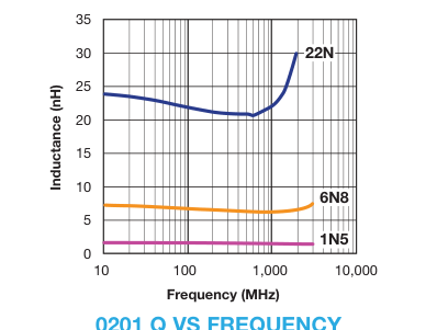
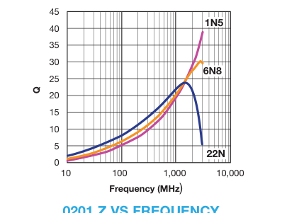
0201 Z VS FREQUENCY
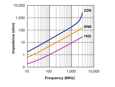
Page 5
LCMC Series
ELECTRICAL CHARACTERISTICS
0402
| Ordering Code | Inductance (nH) | Available Tolerance | Q Min. | L, Q Measuring Frequency (MHz) | Self- Resonance Frequency (MHz) | DC Resistance (Ω) | Rated Current (mA) Max. | Packing Amount of 7" Reel Pcs | ||
|---|---|---|---|---|---|---|---|---|---|---|
| Min. | Typ. | Max. | Typ. | |||||||
| 0N6 | 0.6 | ±0.3nH, ±0.2nH, ±0.1nH | 8 | 100 | 10000 | >13000 | 0.08 | 0.02 | 300 | 10,000 |
| 1N0 | 1.0 | ±0.3nH, ±0.2nH, ±0.1nH | 8 | 100 | 10000 | >13000 | 0.08 | 0.02 | 300 | |
| 1N1 | 1.1 | ±0.3nH, ±0.2nH, ±0.1nH | 8 | 100 | 10000 | >13000 | 0.08 | 0.03 | 300 | |
| 1N2 | 1.2 | ±0.3nH, ±0.2nH, ±0.1nH | 8 | 100 | 10000 | >13000 | 0.09 | 0.03 | 300 | |
| 1N3 | 1.3 | ±0.3nH, ±0.2nH, ±0.1nH | 8 | 100 | 10000 | >13000 | 0.09 | 0.04 | 300 | |
| 1N5 | 1.5 | ±0.3nH, ±0.2nH, ±0.1nH | 8 | 100 | 10000 | >13000 | 0.10 | 0.05 | 300 | |
| 1N6 | 1.6 | ±0.3nH, ±0.2nH, ±0.1nH | 8 | 100 | 10000 | >13000 | 0.10 | 0.05 | 300 | |
| 1N8 | 1.8 | ±0.3nH, ±0.2nH, ±0.1nH | 8 | 100 | 6000 | 12220 | 0.12 | 0.05 | 300 | |
| 2N0 | 2.0 | ±0.3nH, ±0.2nH, ±0.1nH | 8 | 100 | 6000 | 12890 | 0.12 | 0.06 | 300 | |
| 2N2 | 2.2 | ±0.3nH, ±0.2nH, ±0.1nH | 8 | 100 | 6000 | 12430 | 0.13 | 0.06 | 300 | |
| 2N4 | 2.4 | ±0.3nH, ±0.2nH, ±0.1nH | 8 | 100 | 6000 | 12320 | 0.13 | 0.07 | 300 | |
| 2N7 | 2.7 | ±0.3nH, ±0.2nH, ±0.1nH | 8 | 100 | 6000 | 10070 | 0.16 | 0.09 | 300 | |
| 3N0 | 3.0 | ±0.3nH, ±0.2nH, ±0.1nH | 8 | 100 | 6000 | 8760 | 0.16 | 0.09 | 300 | |
| 3N3 | 3.3 | ±0.3nH, ±0.2nH, ±0.1nH | 8 | 100 | 6000 | 8120 | 0.16 | 0.09 | 300 | |
| 3N6 | 3.6 | ±0.3nH, ±0.2nH, ±0.1nH | 8 | 100 | 5000 | 8200 | 0.20 | 0.10 | 300 | |
| 3N9 | 3.9 | ±0.3nH, ±0.2nH, ±0.1nH | 8 | 100 | 4000 | 8390 | 0.20 | 0.10 | 300 | |
| 4N3 | 4.3 | ±0.3nH, ±0.2nH, ±0.1nH | 8 | 100 | 4000 | 7500 | 0.20 | 0.11 | 300 | |
| 4N7 | 4.7 | ±0.3nH, ±0.2nH, ±0.1nH | 8 | 100 | 4000 | 7010 | 0.20 | 0.11 | 300 | |
| 5N1 | 5.1 | ±0.3nH, ±0.2nH, ±0.1nH | 8 | 100 | 4000 | 6340 | 0.23 | 0.13 | 300 | |
| 5N6 | 5.6 | ±0.3nH, ±0.2nH, ±0.1nH | 8 | 100 | 4000 | 5760 | 0.23 | 0.13 | 300 | |
| 6N2 | 6.2 | ±0.3nH, ±0.2nH, ±0.1nH | 8 | 100 | 3900 | 5490 | 0.25 | 0.15 | 300 | |
| 6N8 | 6.8 | ±5%, ±3%, ±2% | 8 | 100 | 3900 | 5430 | 0.25 | 0.14 | 300 | |
| 7N5 | 7.5 | ±5%, ±3%, ±2% | 8 | 100 | 3700 | 5000 | 0.28 | 0.16 | 300 | |
| 8N2 | 8.2 | ±5%, ±3%, ±2% | 8 | 100 | 3500 | 4660 | 0.28 | 0.17 | 300 | |
| 9N1 | 9.1 | ±5%, ±3%, ±2% | 8 | 100 | 3400 | 4400 | 0.30 | 0.22 | 300 | |
| 10N | 10 | ±5%, ±3%, ±2% | 8 | 100 | 3200 | 4120 | 0.31 | 0.24 | 300 | |
| 12N | 12 | ±5%, ±3%, ±2% | 8 | 100 | 2600 | 3820 | 0.45 | 0.30 | 300 | |
| 15N | 15 | ±5%, ±3%, ±2% | 8 | 100 | 2300 | 3350 | 0.55 | 0.38 | 300 | |
| 18N | 18 | ±5%, ±3%, ±2% | 8 | 100 | 2000 | 2970 | 0.65 | 0.37 | 300 | |
| 22N | 22 | ±5% ±3%,, ±2% | 8 | 100 | 1600 | 2640 | 0.70 | 0.45 | 300 | |
| 27N | 27 | ±5%, ±3%, ±2% | 8 | 100 | 1400 | 2370 | 0.80 | 0.49 | 300 | |
| 33N | 33 | ±5%, ±3%, ±2% | 8 | 100 | 1200 | 2040 | 0.90 | 0.63 | 200 | |
| 39N | 39 | ±5%, ±3%, ±2% | 8 | 100 | 1100 | 1800 | 1.00 | 0.70 | 200 | |
| 47N | 47 | ±5%, ±3%, ±2% | 8 | 100 | 900 | 1660 | 1.10 | 0.82 | 200 | |
| 56N | 56 | ±5%, ±3%, ±2% | 8 | 100 | 750 | 1560 | 1.10 | 0.84 | 200 | |
| 68N | 68 | ±5%, ±3%, ±2% | 8 | 100 | 750 | 1330 | 1.20 | 0.99 | 180 | |
| 82N | 82 | ±5%, ±3%, ±2% | 8 | 100 | 600 | 1160 | 1.30 | 1.09 | 150 | |
| R10 | 100 | ±5% | 8 | 100 | 600 | 1020 | 1.60 | 1.19 | 150 | |
| R12 | 120 | ±5% | 8 | 100 | 600 | 860 | 1.60 | 1.31 | 150 | |
| R15 | 150 | ±5% | 8 | 100 | 550 | 800 | 2.40 | 1.58 | 140 | |
| R18 | 180 | ±5% | 8 | 100 | 500 | 810 | 3.70 | 2.97 | 130 | |
| R22 | 220 | ±5% | 8 | 100 | 450 | 700 | 4.20 | 3.29 | 120 | |
| R27 | 270 | ±5% | 8 | 100 | 400 | 600 | 4.80 | 3.92 | 110 | |
Tolerance: B = ±0.1nH, C = ±0.2nH, S = ±0.3nH, G = ±2%, H = ±3%, J = ±5%, K = ±10% Measuring Equipment: HP4287+16196C Measuring Temperature: 25 ± 3ºC Operating Temperature: -55ºC to +125ºC
Page 6
LCMC Series
L, Q VS. FREQUENCY CHARACTERISTICS
0402
| Ordering Code | Typical Inductance (nH) | Typical Q | ||||||||||||
|---|---|---|---|---|---|---|---|---|---|---|---|---|---|---|
| 100 MHz | 500 MHz | 800 MHz | 900 MHz | 1.8 GHz | 2.0 GHz | 2.4 GHz | 100 MHz | 500 MHz | 800 MHz | 900 MHz | 1.8 GHz | 2.0 GHz | 2.4 GHz | |
| 0N6 | 0.6 | 0.6 | 0.6 | 0.6 | 0.6 | 0.6 | 0.6 | 12 | 40 | 60 | 65 | 100 | 120 | 140 |
| 1N0 | 1.0 | 1.0 | 1.0 | 1.0 | 1.0 | 1.0 | 1.0 | 12 | 29 | 38 | 41 | 63 | 71 | 75 |
| 1N1 | 1.1 | 1.1 | 1.1 | 1.1 | 1.1 | 1.1 | 1.1 | 11 | 29 | 37 | 40 | 60 | 67 | 72 |
| 1N2 | 1.2 | 1.2 | 1.2 | 1.2 | 1.2 | 1.2 | 1.2 | 11 | 29 | 38 | 41 | 61 | 68 | 73 |
| 1N3 | 1.3 | 1.3 | 1.3 | 1.3 | 1.3 | 1.3 | 1.3 | 11 | 30 | 38 | 41 | 61 | 67 | 72 |
| 1N5 | 1.5 | 1.5 | 1.5 | 1.5 | 1.5 | 1.5 | 1.5 | 11 | 27 | 35 | 38 | 57 | 63 | 68 |
| 1N6 | 1.6 | 1.5 | 1.5 | 1.5 | 1.5 | 1.5 | 1.5 | 11 | 28 | 35 | 38 | 57 | 64 | 68 |
| 1N8 | 1.8 | 1.7 | 1.7 | 1.7 | 1.7 | 1.7 | 1.8 | 11 | 26 | 33 | 36 | 53 | 58 | 61 |
| 2N0 | 2.0 | 2.0 | 2.0 | 2.0 | 2.0 | 2.1 | 2.1 | 10 | 23 | 29 | 31 | 45 | 49 | 52 |
| 2N2 | 2.2 | 2.1 | 2.1 | 2.1 | 2.2 | 2.2 | 2.2 | 10 | 24 | 31 | 33 | 48 | 52 | 55 |
| 2N4 | 2.4 | 2.3 | 2.3 | 2.3 | 2.4 | 2.4 | 2.4 | 10 | 25 | 31 | 34 | 49 | 53 | 57 |
| 2N7 | 2.7 | 2.7 | 2.7 | 2.7 | 2.8 | 2.8 | 2.9 | 11 | 27 | 35 | 37 | 54 | 58 | 60 |
| 3N0 | 3.0 | 2.9 | 2.9 | 3.0 | 3.1 | 3.1 | 3.2 | 10 | 25 | 32 | 34 | 49 | 53 | 55 |
| 3N3 | 3.3 | 3.2 | 3.2 | 3.2 | 3.4 | 3.4 | 3.5 | 11 | 25 | 32 | 35 | 50 | 54 | 56 |
| 3N6 | 3.6 | 3.5 | 3.5 | 3.5 | 3.7 | 3.8 | 3.9 | 10 | 24 | 31 | 33 | 46 | 49 | 49 |
| 3N9 | 3.9 | 3.7 | 3.7 | 3.8 | 3.9 | 4.0 | 4.1 | 11 | 24 | 30 | 33 | 46 | 49 | 51 |
| 4N3 | 4.3 | 4.1 | 4.2 | 4.2 | 4.4 | 4.4 | 4.6 | 11 | 26 | 33 | 35 | 50 | 53 | 54 |
| 4N7 | 4.7 | 4.5 | 4.5 | 4.5 | 4.8 | 4.9 | 5.1 | 11 | 25 | 32 | 35 | 49 | 51 | 53 |
| 5N1 | 5.1 | 4.9 | 4.9 | 4.9 | 5.2 | 5.3 | 5.6 | 11 | 25 | 32 | 35 | 46 | 48 | 49 |
| 5N6 | 5.6 | 5.5 | 5.5 | 5.5 | 6.0 | 6.2 | 6.7 | 11 | 25 | 32 | 35 | 46 | 48 | 49 |
| 6N2 | 6.2 | 6.1 | 6.1 | 6.1 | 6.7 | 6.8 | 7.3 | 11 | 26 | 32 | 34 | 46 | 48 | 49 |
| 6N8 | 6.8 | 6.6 | 6.7 | 6.7 | 7.4 | 7.6 | 8.2 | 11 | 26 | 32 | 35 | 46 | 48 | 48 |
| 7N5 | 7.5 | 7.1 | 7.2 | 7.3 | 7.8 | 8.1 | 8.8 | 11 | 26 | 32 | 35 | 46 | 48 | 48 |
| 8N2 | 8.2 | 8.0 | 8.1 | 8.2 | 9.4 | 9.9 | 11.1 | 11 | 26 | 32 | 34 | 42 | 42 | 40 |
| 9N1 | 9.1 | 8.7 | 8.8 | 8.8 | 9.9 | 10.2 | 11.1 | 11 | 25 | 31 | 34 | 42 | 42 | 40 |
| 10N | 10.0 | 10.0 | 9.8 | 9.9 | 11.7 | 12.4 | 14.4 | 11 | 23 | 29 | 31 | 37 | 37 | 34 |
| 12N | 12.0 | 11.7 | 12.0 | 12.2 | 15.1 | 16.3 | 20.1 | 11 | 24 | 31 | 33 | 37 | 36 | 30 |
| 15N | 15.0 | 14.9 | 15.5 | 15.8 | 22.8 | 26.4 | 41.8 | 11 | 23 | 30 | 32 | 35 | 33 | 28 |
| 18N | 18.0 | 17.8 | 18.4 | 18.7 | 24.9 | 27.7 | 37.7 | 11 | 23 | 28 | 29 | 30 | 28 | 22 |
| 22N | 22.0 | 21.8 | 23.1 | 23.8 | 40.9 | 52.7 | 156.0 | 11 | 22 | 27 | 28 | 22 | 18 | 6 |
| 27N | 27.0 | 27.1 | 29.2 | 30.3 | 66.8 | 106.9 | – | 11 | 22 | 26 | 27 | 16 | 11 | 4 |
| 33N | 33.0 | 33.2 | 36.3 | 37.9 | 109.0 | 259.0 | – | 11 | 22 | 25 | 26 | 12 | 5 | – |
| 39N | 39.0 | 40.2 | 45.9 | 49.1 | – | – | – | 11 | 20 | 22 | 22 | – | – | – |
| 47N | 47.0 | 49.1 | 57.2 | 61.7 | – | – | – | 11 | 20 | 21 | 21 | – | – | – |
| 56N | 56.0 | 59.2 | 71.8 | 79.3 | – | – | – | 11 | 19 | 19 | 18 | – | – | – |
| 68N | 68.0 | 74.7 | 99.4 | 116.3 | – | – | – | 11 | 18 | 17 | 15 | – | – | – |
| 82N | 82.0 | 94.7 | 140.8 | 179.5 | – | – | – | 11 | 18 | 15 | 12 | – | – | – |
| R10 | 100.0 | 117.6 | 193.7 | 269.9 | – | – | – | 11 | 17 | 12 | 9 | – | – | – |
| R12 | 120.0 | 159.8 | 450.4 | – | – | – | – | 11 | 16 | 7 | – | – | – | – |
| R15 | 150.0 | 207.2 | – | – | – | – | – | 11 | 14 | – | – | – | – | – |
| R18 | 180.0 | – | – | – | – | – | – | 12 | – | – | – | – | – | – |
| R22 | 220.0 | – | – | – | – | – | – | 12 | – | – | – | – | – | – |
| R27 | 270.0 | – | – | – | – | – | – | 12 | – | – | – | – | – | – |
Page 7
LCMC Series
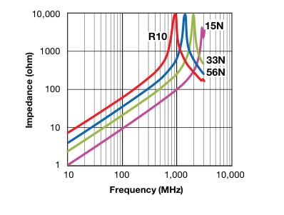
0402 L VS FREQUENCY
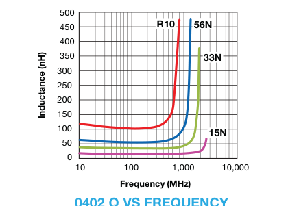
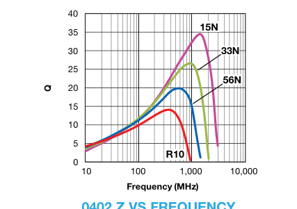
0402 Z VS FREQUENCY
Page 8
LCMC Series
ELECTRICAL CHARACTERISTICS
0603
| Ordering Code | Inductance (nH) | Available Tolerance | Q Min. | L, Q Measuring Frequency (MHz) | Self- Resonance Frequency (MHz) | DC Resistance (Ω) | Rated Current (mA) Max. | Packing Amount of 7" Reel Pcs | ||
|---|---|---|---|---|---|---|---|---|---|---|
| Min. | Typ. | Max. | Typ. | |||||||
| 1N0 | 1.0 | ±0.3nH, ±0.2nH, ±0.1nH | 8 | 100 | 10000 | >13000 | 0.05 | 0.01 | 1000 | 4,000 |
| 1N2 | 1.2 | ±0.3nH, ±0.2nH, ±0.1nH | 8 | 100 | 10000 | >13000 | 0.05 | 0.02 | 1000 | |
| 1N5 | 1.5 | ±0.3nH, ±0.2nH, ±0.1nH | 8 | 100 | 10000 | >13000 | 0.10 | 0.03 | 1000 | |
| 1N8 | 1.8 | ±0.3nH, ±0.2nH, ±0.1nH | 8 | 100 | 10000 | >13000 | 0.10 | 0.04 | 1000 | |
| 2N2 | 2.2 | ±0.3nH, ±0.2nH, ±0.1nH | 8 | 100 | 6000 | 11690 | 0.10 | 0.05 | 1000 | |
| 2N7 | 2.7 | ±0.3nH, ±0.2nH, ±0.1nH | 10 | 100 | 6000 | 8930 | 0.13 | 0.06 | 1000 | |
| 3N3 | 3.3 | ±0.3nH, ±0.2nH, ±0.1nH | 10 | 100 | 6000 | 6440 | 0.13 | 0.07 | 1000 | |
| 3N9 | 3.9 | ±0.3nH, ±0.2nH, ±0.1nH | 10 | 100 | 6000 | 7280 | 0.15 | 0.08 | 1000 | |
| 4N7 | 4.7 | ±0.3nH, ±0.2nH, ±0.1nH | 10 | 100 | 4000 | 6470 | 0.20 | 0.09 | 1000 | |
| 5N6 | 5.6 | ±0.3nH, ±0.2nH, ±0.1nH | 10 | 100 | 4000 | 5230 | 0.23 | 0.10 | 600 | |
| 6N8 | 6.8 | ±5%, ±2% | 10 | 100 | 4000 | 5470 | 0.25 | 0.11 | 600 | |
| 8N2 | 8.2 | ±5%, ±2% | 10 | 100 | 3500 | 4460 | 0.28 | 0.14 | 600 | |
| 10N | 10 | ±5%, ±2% | 12 | 100 | 3200 | 4360 | 0.30 | 0.15 | 600 | |
| 12N | 12 | ±5%, ±2% | 12 | 100 | 2600 | 3480 | 0.35 | 0.17 | 600 | |
| 15N | 15 | ±5%, ±2% | 12 | 100 | 2300 | 3310 | 0.40 | 0.19 | 600 | |
| 18N | 18 | ±5%, ±2% | 12 | 100 | 2000 | 3080 | 0.45 | 0.21 | 600 | |
| 22N | 22 | ±5%, ±2% | 12 | 100 | 1600 | 2670 | 0.50 | 0.29 | 600 | |
| 27N | 27 | ±5%, ±2% | 12 | 100 | 1400 | 2270 | 0.55 | 0.27 | 600 | |
| 33N | 33 | ±5%, ±2% | 12 | 100 | 1200 | 1970 | 0.60 | 0.36 | 600 | |
| 39N | 39 | ±5%, ±2% | 12 | 100 | 1100 | 1830 | 0.65 | 0.37 | 500 | |
| 47N | 47 | ±5%, ±2% | 12 | 100 | 900 | 1670 | 0.70 | 0.47 | 500 | |
| 56N | 56 | ±5%, ±2% | 12 | 100 | 900 | 1530 | 0.75 | 0.46 | 500 | |
| 68N | 68 | ±5%, ±2% | 12 | 100 | 700 | 1360 | 0.85 | 0.51 | 400 | |
| 82N | 82 | ±5%, ±2% | 12 | 100 | 600 | 1290 | 0.95 | 0.57 | 300 | |
| R10 | 100 | ±5%, ±2% | 12 | 100 | 600 | 1090 | 1.00 | 0.69 | 300 | |
| R12 | 120 | ±5%, ±2% | 8 | 50 | 500 | 1030 | 1.20 | 0.74 | 300 | |
| R15 | 150 | ±5%, ±2% | 8 | 50 | 500 | 820 | 1.20 | 0.78 | 300 | |
| R18 | 180 | ±5%, ±2% | 8 | 50 | 400 | 690 | 1.30 | 0.92 | 300 | |
| R22 | 220 | ±5%, ±2% | 8 | 50 | 400 | 630 | 1.50 | 1.19 | 300 | |
| R24 | 240 | ±5%, ±2% | 8 | 50 | 400 | 600 | 1.70 | 1.20 | 200 | |
| R27 | 270 | ±5%, ±2% | 8 | 50 | 400 | 520 | 1.90 | 1.30 | 150 | |
| R33R | 330 | ±5%, ±2% | 8 | 50 | 350 | 450 | 2.10 | 1.50 | 150 | |
| R39 | 390 | ±5%, ±2% | 8 | 50 | 350 | 400 | 2.30 | 1.80 | 150 | |
| R47 | 470 | ±5%, ±2% | 8 | 50 | 300 | 360 | 2.60 | 2.04 | 150 | |
Tolerance: B = ±0.1nH, C = ±0.2nH, S = ±0.3nH, G = ±2%, H = ±3%, J = ±5%, K = ±10% Measuring Equipment: HP4291B+16192A Measuring Temperature: 25 ± 3ºC Operating Temperature: -40ºC to +125ºC
Page 9
LCMC Series
L, Q VS. FREQUENCY CHARACTERISTICS
0603
| Ordering Code | Typical Inductance (nH) | Typical Q | ||||||||||||
|---|---|---|---|---|---|---|---|---|---|---|---|---|---|---|
| 100 MHz | 500 MHz | 800 MHz | 900 MHz | 1.8 GHz | 2.0 GHz | 2.4 GHz | 100 MHz | 500 MHz | 800 MHz | 900 MHz | 1.8 GHz | 2.0 GHz | 2.4 GHz | |
| 1N0 | 1.0 | 1.1 | 1.1 | 1.1 | 1.1 | 1.1 | 1.0 | 14 | 40 | 53 | 60 | 93 | 32 | 174 |
| 1N2 | 1.2 | 1.2 | 1.2 | 1.2 | 1.2 | 1.2 | 1.1 | 14 | 38 | 49 | 54 | 84 | 32 | 143 |
| 1N5 | 1.5 | 1.6 | 1.6 | 1.6 | 1.6 | 1.5 | 1.5 | 12 | 31 | 39 | 43 | 62 | 33 | 88 |
| 1N8 | 1.8 | 1.8 | 1.8 | 1.8 | 1.8 | 1.8 | 1.7 | 13 | 34 | 42 | 46 | 68 | 37 | 97 |
| 2N2 | 2.2 | 2.2 | 2.2 | 2.2 | 2.2 | 2.2 | 2.2 | 14 | 36 | 46 | 50 | 73 | 42 | 101 |
| 2N7 | 2.7 | 2.7 | 2.7 | 2.7 | 2.7 | 2.7 | 2.7 | 14 | 36 | 47 | 45 | 72 | 45 | 94 |
| 3N3 | 3.3 | 3.3 | 3.3 | 3.3 | 3.5 | 3.5 | 3.6 | 14 | 37 | 47 | 50 | 67 | 47 | 77 |
| 3N9 | 3.9 | 3.9 | 3.9 | 3.9 | 4.0 | 4.0 | 4.1 | 15 | 36 | 46 | 49 | 66 | 48 | 81 |
| 4N7 | 4.7 | 4.6 | 4.6 | 4.7 | 4.9 | 4.9 | 5.1 | 15 | 39 | 50 | 53 | 70 | 53 | 80 |
| 5N6 | 5.6 | 5.5 | 5.6 | 5.6 | 6.1 | 6.3 | 6.7 | 15 | 39 | 50 | 54 | 67 | 52 | 69 |
| 6N8 | 6.8 | 6.7 | 6.7 | 6.8 | 7.3 | 7.5 | 7.9 | 15 | 38 | 49 | 52 | 66 | 53 | 66 |
| 8N2 | 8.2 | 8.1 | 8.2 | 8.3 | 9.5 | 9.9 | 11.0 | 16 | 37 | 48 | 50 | 59 | 49 | 54 |
| 10N | 10.0 | 9.9 | 10.1 | 10.2 | 11.7 | 12.3 | 13.9 | 16 | 39 | 49 | 52 | 60 | 50 | 52 |
| 12N | 12.0 | 12.2 | 12.6 | 12.8 | 16.6 | 18.4 | 24.4 | 16 | 36 | 46 | 48 | 47 | 39 | 31 |
| 15N | 15.0 | 15.1 | 15.6 | 15.9 | 21.0 | 23.4 | 31.9 | 17 | 40 | 50 | 52 | 49 | 41 | 31 |
| 18N | 18.0 | 18.1 | 18.9 | 19.3 | 27.7 | 32.2 | 52.2 | 17 | 39 | 48 | 50 | 43 | 35 | 21 |
| 22N | 22.0 | 22.3 | 23.8 | 24.6 | 45.7 | 63.5 | 521.1 | 17 | 39 | 46 | 47 | 29 | 19 | 1 |
| 27N | 27.0 | 27.8 | 30.3 | 31.6 | 85.8 | 191.2 | – | 18 | 39 | 45 | 46 | 19 | 8 | – |
| 33N | 33.0 | 34.9 | 38.8 | 40.9 | – | – | – | 18 | 39 | 43 | 43 | – | – | – |
| 39N | 39.0 | 41.3 | 47.7 | 51.2 | – | – | – | 19 | 36 | 39 | 37 | – | – | – |
| 47N | 47.0 | 50.0 | 58.9 | 64.0 | – | – | – | 17 | 34 | 36 | 34 | – | – | – |
| 56N | 56.0 | 62.0 | 77.7 | 87.5 | – | – | – | 19 | 35 | 34 | 31 | – | – | – |
| 68N | 68.0 | 76.8 | 103.2 | 121.7 | – | – | – | 18 | 33 | 29 | 25 | – | – | – |
| 82N | 82.0 | 96.5 | 145.3 | 187.2 | – | – | – | 19 | 32 | 25 | 20 | – | – | – |
| R10 | 100.0 | 123.7 | 222.4 | 343.5 | – | – | – | 18 | 30 | 19 | 12 | – | – | – |
| R12 | 120.0 | 156.0 | 355.0 | – | – | – | – | 19 | 28 | 14 | – | – | – | – |
| R15 | 150.0 | 227.9 | – | – | – | – | – | 18 | 21 | – | – | – | – | – |
| R18 | 180.0 | 336.8 | – | – | – | – | – | 17 | 17 | – | – | – | – | – |
| R22 | 220.0 | 520.7 | – | – | – | – | – | 16 | 13 | – | – | – | – | – |
| R24 | 240.0 | 16 | ||||||||||||
| R27 | 270.0 | – | – | – | – | – | – | 16 | – | – | – | – | – | – |
| R33R | 330.0 | – | – | – | – | – | – | 14 | – | – | – | – | – | – |
| R39 | 390.0 | – | – | – | – | – | – | 14 | – | – | – | – | – | – |
| R47 | 470.0 | – | – | – | – | – | – | 13 | – | – | – | – | – | – |
Page 10
LCMC Series
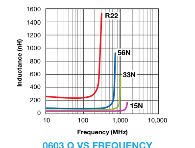
0603 L VS FREQUENCY
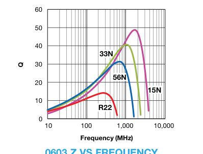
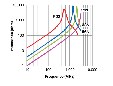
0603 Z VS FREQUENCY
Page 11
LCMC Series
TEST CONDITION AND REQUIREMENTS
| No. | Item | Test Condition | Requirements |
|---|---|---|---|
| 1 | Inductance | a. Temperature: 25 ± 3ºC c. Measuring equipment and fixture: b. Relative Humidity: 45 to 75%RH (0603) HP 4291+16192A (0402) HP 4287+16193A (0201) HP 4287+16196C | Within specified tolerance. |
| 2 | Q Value | a. Temperature: 25 ± 3ºC c. Measuring equipment and fixture: b. Relative Humidity: 45 to 75%RH (0603) HP 4291+16192A (0402) HP 4287+16193A (0201) HP 4287+16196C | In accordance with electrical specification. |
| 3 | DC Resistance | a. Temperature: 25 ± 3ºC b. Relative Humidity: 45 to 75%RH c. Measuring equipment: HP 4338. | In accordance with electrical specification. |
| 4 | Appearance | Inductors shall be visually inspected for visible evidence of defect. | In accordance with specification. |
| 5 | Dimension | Dimension shall be measured with caliper or micrometer | In accordance with dimension specification. |
| 6 | Solderability | Immerse a test sample into a methanol solution containing resin and immerse into molten solder of 230 ± 5ºC for 5 ± 1 second. | More than 75% of the terminal electrode part shall be covered with fresh solder. |
| 7 | Bending Strength | Solder the chip to test jig then apply a force in the direction shown in below. The soldering shall be done with the reflow method and shall be conducted with care so that the soldering is uniform and free of defects such as heat shock. Mounting Samples Test PC Board Sample 20 Press R230 Supports (Ø5) 50 Press Jig Solder 45±2mm 45±2mm Amplitude 2mm | 1. No mechanical damage shall be observed. 2. Rdc-value: to meet the initial Spec. |
| 8 | Resistance to Soldering Heat | Immerse a test sample into a methanol solution containing resin, preheat it at 120 to 150ºC for 1 minute and immerse into molten solder of 270 ± 5ºC for 10 ± 1 second so that both terminal electrodes are completely submerged. | No visible damage. Inductance variation within 10%. Q variation within 20%. |
| 9 | Thermal Shock | Solder a test sample to printed circuit board, and conduct 5 cycles of test under the conditions shown as below. 0201 & 0402 operating temp. range: -55~125ºC 0603 operating temp. range: -40~85ºC Cycle: Maximum operating temp. (30 ± 3min) within 3min Minimum operating temp. (30 ± 3min) | No visible damage. Inductance variation within 10%. Q variation within 20%. |
| 10 | High Humidity State Life Test | Keep a test sample in an atmosphere with a temperature of 40 ± 2ºC, 90~95%RH for 500 ± 12 hours. After the removal from test chamber, 2 to 3 hours of recovery under standard condition, and measurement shall be made after 24 ± 2 hrs. of recovery under standard condition. | No visible damage. Inductance variation within 10%. Q variation within 20%. |
| 11 | High Humidity Load Life Test | Solder a test sample to printed circuit board then keep the test sample in an atmosphere with a temperature of 40 ± 2ºC, 90~95%RH for 500 ± 12 hours while supplying the rated current. After the removal from test chamber, 2 to 3 hours of recovery under standard condition, and measurement shall be made after 24 ± 2 hrs. of recovery under standard condition. | No visible damage. Inductance variation within 10%. Q variation within 20%. |
| 12 | High Temperature State Life Test | Keep a test sample in an atmosphere with a temperature of 85 ± 2ºC for 500 ± 12 hours. After the removal from test chamber, 2 to 3 hours of recovery under standard condition, and measurement shall be made after 24 ± 2 hrs. of recovery under standard condition. | No visible damage. Inductance variation within 10%. Q variation within 20%. |
| 13 | High Temperature Load | Solder a test sample to printed circuit board then keep the test sample in an atmosphere with a temperature of 85 ± 2ºC for 500 ± 12 hours while supplying the rated current. After the removal from test chamber, 2 to 3 hours of recovery under standard condition, and measurement shall be made after 24 ± 2 hrs. of recovery under standard condition. | No visible damage. Inductance variation within 10%. Q variation within 20%. |
Page 12
LCMC Series
PACKAGING SPECIFICATIONS
Paper tape specification (0201/0402/0603)
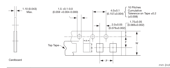
| Symbol | Product Size Code | |||||
|---|---|---|---|---|---|---|
| 0201 | 0402 | 0603 | ||||
| Size | Tolerance | Size | Tolerance | Size | Tolerance | |
| A | 0.38 (0.015) | ± 0.02 (0.001) | 0.62 (0.024) | ± 0.03 (0.001) | 0.975 (0.038) | ± 0.05 (0.002) |
| B | 0.68 (0.027) | ± 0.02 (0.001) | 1.12 (0.044) | ± 0.03 (0.001) | 1.80 (0.071) | ± 0.05 (0.002) |
| F | 3.50 (0.138) | ± 0.05 (0.002) | 3.50 (0.138) | ± 0.05 (0.002) | 3.50 (0.138) | ± 0.05 (0.002) |
| P | 2.00 (0.079) | ± 0.10 (0.004) | 2.00 (0.079) | ± 0.10 (0.004) | 4.00 (0.157) | ± 0.10 (0.004) |
| W | 8.00 (0.315) | ± 0.20 (0.008) | 8.00 (0.315) | ± 0.20 (0.008) | 8.00 (0.315) | ± 0.20 (0.008) |
Reel Specifications
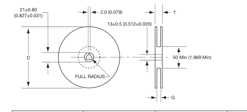
mm (inches)
| Tape Width | G | T max. | D |
|---|---|---|---|
| 8.00 (0.315) | 10.0 ± 1.5 (0.394 ± 0.059) | 14.5 (0.571) | 180 (7.087) |
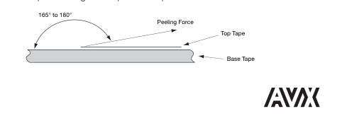
Peel strength of top cover tape
The peel speed shall be about 300 mm/min.
The peel strength of top cover tape shall be between 0.1 to 1.0N.
Page 13
LCMC Series
Quantity per reel
0201: 15,000 pieces / reel 0402: 10,000 pieces / reel 0603: 4,000 pieces / reel
The contents of a box
0201: 5 reels / box 0402: 5 reels / box 0603: 5 reels / box
CAUTIONS
Storage
The chip inductor shall be packaged in carrier tapes. To keep storage place temperature from +5 to 35ºC, humidity from 45 to 70% RH. The storage atmosphere must be free of gas containing sulfur and chlorine. Also, avoid exposing the product to saline moisture. If the product is exposed to such atmospheres, the terminals will oxidize and solderability will be affected. The solderability is assured for 12 months from our final inspection date if the above storage condition is followed.
Handling
Chip inductor should be handled with care to avoid contamination or damage. The use of vacuum pick-up or plastic tweezers is recommended for manual placement. Tape and reeled packages are suitable for automatic pick and placement machine.
Recommended pad dimensions
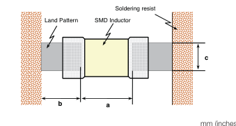
| Size (EIA) | L x W | a | b | c |
| 0201 | 0.60 x 0.30 (0.024 x 0.012) | 0.15 to 0.35 (0.006 to 0.014) | 0.20 to 0.30 (0.008 to 0.012) | 0.25 to 0.30 (0.010 to 0.012) |
| 0402 | 1.00 x 0.50 (0.039 x 0.020) | 0.30 to 0.50 (0.012 to 0.020) | 0.35 to 0.45 (0.014 to 0.018) | 0.40 to 0.50 (0.016 to 0.020) |
| 0603 | 1.60 x 0.80 (0.063 x 0.031) | 0.70 to 1.00 (0.028 to 0.039) | 0.60 to 0.80 (0.024 to 0.031) | 0.70 to 0.80 (0.028 to 0.031) |
Marking
The following item shall be marked on the reel. a. Manufactures parts number. b. Manufacturing date code. c. Manufacturer name. d. Manufactures lot number. e. Quantity.
Soldering Profile for SMT Process with SnPb Solder Paste
The rate of preheat should not exceed 4ºC/sec. and a target of 2ºC/sec. is preferred. Ceramic chip components should be preheated to within 100 to 130ºC of the soldering.
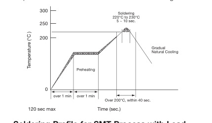
Soldering Profile for SMT Process with Lead Free Solder Paste
The rate of preheat should not exceed 4ºC/sec. and a target of 2ºC/sec. is preferred. Ceramic chip components should be preheated to within 100 to 130ºC of the soldering.