
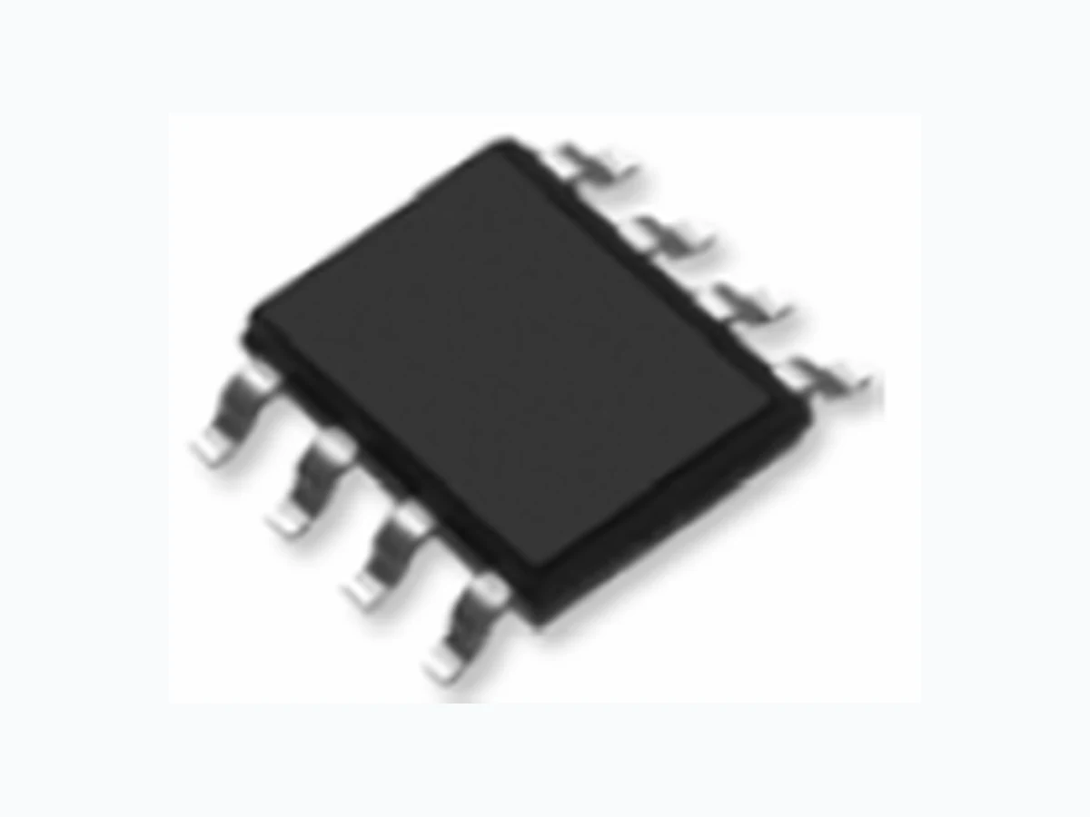
LCE30ND07S LEIDITECH
Document overview
- Manufacturer or author: Provided By www.digicamel.com(FREE DATASHEET DOWNLOAD SITE)
- PDF pages: 6
Technical content
Description
The LCE30ND07S uses advanced trench technology and design to provide excellent R DS(ON) with low gate charge. It can be used in a wide variety of applications. General Features
- V DS =30V,I D =7A R DS(ON) < 23mΩ @ V GS =10V R DS(ON) < 40mΩ @ V GS =4.5V
- High density cell design for ultra low Rdson
- Fully characterized avalanche voltage and current Application
- Power switching application
- Hard switched and high frequency circuits
- Uninterruptible power supply Schematic diagram Marking and pin Assignment SOP-8 top view Package Marking and Ordering Information Device Marking Device Device Package Reel Size Tape width Quantity 30ND07S LCE30ND07S SOP-8 Ø330mm 12mm 2500 units Absolute Maximum Ratings (T A =25℃unless otherwise noted) Parameter Symbol Limit Unit Drain-Source Voltage V DS 30 V Gate-Source Voltage V GS ±20 V Drain Current-Continuous I D 7 A Drain Current-Continuous(T C =100℃) I D (100℃) 4.95 A Pulsed Drain Current I DM 40 A Maximum Power Dissipation P D 2 W Operating Junction and Storage Temperature Range T J STG -55 To 150 ℃ Thermal Characteristic Parameter Symbol Typ Max Unit Thermal Resistance,Junction-to-Ambient (Note 2) R θJA 62.5 85 ℃/W LCE N-Channel Super Junction Power MOSFET Rev : www.leiditech.com 01.06.2018 1/6
Electrical Characteristics (T A =25℃unless otherwise noted) Parameter Symbol Condition Min Typ Max Unit Off Characteristics Drain-Source Breakdown Voltage BV DSS V GS =0V I D =250μA 30 - - V Zero Gate Voltage Drain Current I DSS V DS =30V,V GS =0V - - 1 μA Gate-Body Leakage Current I GSS V GS =±20V,V DS =0V - - ±100 nA On Characteristics (Note 3) Gate Threshold Voltage V GS(th) V DS GS D =250μA 1.1 - 2.1 V V GS =10V, I D =7A - 18 23 Drain-Source On-State Resistance R DS(ON) V GS =4.5V, I D =6A - 25 40 mΩ Forward Transconductance g FS V DS =5V,I D =7A - 15 - S Dynamic Characteristics (Note4) Input Capacitance C lss - 380 - PF Output Capacitance C oss - 67 - PF Reverse Transfer Capacitance C rss V DS =15V,V GS =0V, F=1.0MHz - 41 - PF Switching Characteristics (Note 4) Turn-on Delay Time t d(on) - 5 - nS Turn-on Rise Time t r - 3 - nS Turn-Off Delay Time t d(off) - 15 - nS Turn-Off Fall Time t f V DD =15V, R L =2Ω V GS =10V,R G =3Ω - 3 - nS Total Gate Charge Q g - 7.2 - nC Gate-Source Charge Q gs - 1.3 - nC Gate-Drain Charge Q gd V DS =15V,I D =7A, V GS =4.5V - 1.7 - nC Drain-Source Diode Characteristics Diode Forward Voltage (Note 3) V SD V GS =0V,I S =7A - - 1.2 V Diode Forward Current (Note 2) I S - - 7 A Notes: 1. Repetitive Rating: Pulse width limited by maximum junction temperature. 2. The value of R θJA is measured with the device mounted on 1in FR-4 board with 2oz. Copper, in a still air environment with T A =25°C. The value in any given application depends on the user's specific board design.Surface Mounted on FR4 Board, t ≤ 10 sec. The current rating is based on the t ≤ 10s thermal resistance rating. 3. Pulse Test: Pulse Width ≤ 300μs, Duty Cycle ≤ 2%. 4. Guaranteed by design, not subject to production. LCE30ND07S Rev : www.leiditech.com 01.06.2018 2/6
1) E AS Test Circuits 2) Gate Charge Test Circuit: 3) Switch Time Test Circuit: LCE30ND07S Rev : www.leiditech.com 01.06.2018 3/6
Dimensions In Millimeters Dimensions In Inches Symbol Min. Max. Min. Max. A 1.350 1.750 0.053 0.069 A1 0.100 0.250 0.004 0.010 A2 1.350 1.550 0.053 0.061 b 0.330 0.510 0.013 0.020 c 0.170 0.250 0.006 0.010 D 4.700 5.100 0.185 0.200 E 3.800 4.000 0.150 0.157 E1 5.800 6.200 0.228 0.244 e 1.270(BSC) 0.050(BSC) L 0.400 1.270 0.016 0.050 θ 0° 8 ° 0 ° 8 ° LCE30ND07S Shanghai Leiditech Electronic Co.,Ltd Email: sale1@leiditech.com Tel : +86- 021 50828806 Fax : +86- 021 50477059 Rev : www.leiditech.com 01.06.2018 6/6