


 Download PDF
LC82101 SANYO
Document overview
- PDF pages: 5
Technical content
Page 1
Ordering number : EN\*4982A
CMOS LSI

Preliminary
Overview
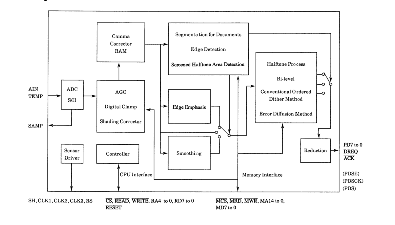
The LC82101 converts an analog image signal from a CCD or contact sensor to high-quality binary image data. The LC82101 uses an internal 8-bit A/D converter for A/D conversion, and in addition to the orthodox dithering technique, also supports an error diffusion technique that allows an even higher quality image to be acquired. These techniques apply to the whole range of processing supported by the LC82101, including full-pixel distortion correction, gamma conversion for arbitrary gamma curves, image compression processing, two-dimensional filtering, halftone processing, and image separation processing to separate documents into text, photograph, and halftone regions. Thus this LSI implements the image
processing required by FAX, copier, and OCR systems.
Features
- Number of pixels processed 2048 pixels/line (64 KB memory, white correction only) 4096 pixels/line (256 KB memory, both white and black correction) 8192 pixels/line (256 KB memory, white correction only)
- Processing speed 500 ns/pixel maximum (The processing time for 1 pixel is 16/SYSCLK.)
- Supports medium speed products with a single external memory chip 100 ns access time memory allows 800 ns/pixel processing, and 60 ns access time memory allows 500 ns/pixel processing.
- AGC (The A/D converter high-level reference voltage is varied from 1.2 to 4.2 V in 0.2 V steps.)
- Built-in 8-bit A/D converter (includes a sensor signal delay adjustment function)
- Sensor drive circuit (supports CCD and all CIS types)
- Digital clamp (single-point clamp, even/odd clamp)
- Distortion correction (white correction, black correction, full-pixel correction)
- Gamma correction (supports user-defined curves)
- Image area separation (text, photographs, halftone)
- Simple binary-conversion processing (fixed threshold level, density-adaptive threshold level)
- Halftone processing Structural dithering (64 levels), settable dithering threshold level Error diffusion technique (64 levels)
- Image reduction (thinning, fine black line retaining, fine white line retaining)
- Single-voltage 5 V supply and low power due to CMOS process fabrication
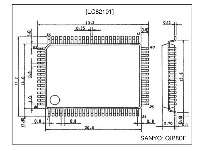
Package Dimensions
unit: mm
3174-QFP80E
SANYO Electric Co.,Ltd. Semiconductor Bussiness Headquarters
TOKYO OFFICE Tokyo Bldg., 1-10, 1 Chome, Ueno, Taito-ku, TOKYO, 110-8534 JAPAN
63095HA (OT) No. 4982-1/5
Page 2
Block Diagram
Pin Functions
Type: I: Input pin, O: Output pin, B: Bidirectional pin, P: Power supply pin, NC: No connection
| Pin No. | Symbol | I/O | Function |
|---|---|---|---|
| 1 | DREQ | O | DMA data request signal output |
| 2 | ACK | I | DMA acknowledge signal input |
| 3 | PD0 | O | Binary image data parallel data bus The data order is set by the MSBF register. Pin 8 can be switched to function as the serial data output valid period signal. Pin 9 can be switched to function as the serial data transfer clock. Pin 10 can be switched to function as the serial data output. |
| 4 | PD1 | O | |
| 5 | PD2 | O | |
| 6 | PD3 | O | |
| 7 | PD4 | O | |
| 8 | PD5/SDE | O | |
| 9 | PD6/SDCK | O | |
| 10 | PD7/SD | O | |
| 11 | MD0 | B | External memory data bus |
| 12 | DVDD | P | Digital system power supply |
| 13 | DGND | P | Digital system ground |
| 14 | MD1 | B | External memory data bus MD7 is the MSB and MD0 is the LSB. |
| 15 | MD2 | B | |
| 16 | MD3 | B | |
| 17 | MD4 | B | |
| 18 | MD5 | B | |
| 19 | MD6 | B | |
| 20 | MD7 | B | |
| 21 | DGND | P | Digital system ground |
| 22 | MA0 | O | External memory address MA14 is the MSB and MA0 is the LSB. |
| 23 | MA1 | O | |
| 24 | MA2 | O | |
| 25 | MA3 | O | |
| 26 | MA4 | O | |
| 27 | MA5 | O | |
| 28 | MA6 | O | |
| 29 | MA7 | O | |
| 30 | MA8 | O |
Continued on next page. No. 4982-2/5
Page 3
Continued from preceding page.
Type: I: Input pin, O: Output pin, B: Bidirectional pin, P: Power supply pin, NC: No connection
| Pin No. | Symbol | I/O | Function |
|---|---|---|---|
| 31 | DVDD | P | Digital system power supply |
| 32 | DGND | P | Digital system ground |
| 33 | MA9 | O | External memory address bus MA14 is the MSB and MA0 is the LSB. |
| 34 | MA10 | O | |
| 35 | MA11 | O | |
| 36 | MA12 | O | |
| 37 | MA13 | O | |
| 38 | MA14 | O | |
| 39 | MCS | O | External memory CS signal |
| 40 | MRD | O | External memory READ signal |
| 41 | MWR | O | External memory WRITE signal |
| 42 | DGND | P | Digital system ground |
| 43 | MTP | O | Motor drive timing signal output |
| 44 | SH | O | Sensor drive signal outputs |
| 45 | RS | O | |
| 46 | CLK1 | O | |
| 47 | CLK2 | O | |
| 48 | CLK3 | O | |
| 49 | SAMP | O | Sampling clock monitor |
| 50 | CLKIN | I | System clock input |
| 51 | DVDD | P | Digital system power supply |
| 52 | DGND | P | Digital system ground |
| 53 | NC | NC | |
| 54 | NC | NC | |
| 55 | NC | NC | |
| 56 | TEST | I | Test input (Connect to ground in normal use.) |
| 57 | AGND | P | Analog system ground |
| 58 | ATAP | O | Analog mid-level connection |
| 59 | AIN | I | Sensor signal input |
| 60 | TEMP | I | Temperature signal input |
| 61 | AVDD | P | Analog system power supply |
| 62 | RD0 | B | CPU interface data bus RD7 is the MSB and RD0 is the LSB. |
| 63 | RD1 | B | |
| 64 | RD2 | B | |
| 65 | RD3 | B | |
| 66 | RD4 | B | |
| 67 | RD5 | B | |
| 68 | RD6 | B | |
| 69 | RD7 | B | |
| 70 | RA0 | I | CPU interface address bus RA4 is the MSB and RA0 is the LSB. |
| 71 | RA1 | I | |
| 72 | RA2 | I | |
| 73 | DVDD | P | Digital system power supply |
| 74 | DGND | P | Digital system ground |
| 75 | RA3 | I | CPU interface address bus |
| 76 | RA4 | I | |
| 77 | CS | I | CPU interface CS signal |
| 78 | READ | I | CPU interface READ signal |
| 79 | WRITE | I | CPU interface WRITE signal |
| 80 | RESET | I | System reset |
No. 4982-3/5
Page 4
Sample Application Circuit
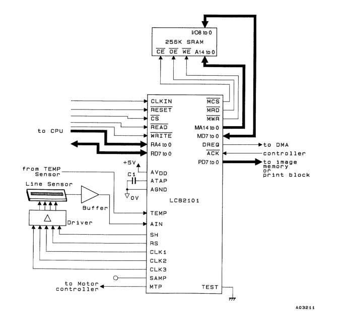
- C1: Use a 0.01 µF laminated ceramic capacitor. 2. Set up the polarity of the image signal from the sensor so that white data is represented by the highest potential and black data by the lowest potential. A level conversion circuit can allow the whole dynamic range of the built-in A/D converter to be used effectively if the maximum output level of the peaks in the image signal from the sensor does not reach 4.2 V. 3. When a 64 K SRAM is used as the distortion correction memory, leave MA11 and MA12 unused and connect MA13 and MA14 to the memory A11 and A12 lines. 4. Although AGND and DGND are completely isolated internally in this LSI, AVDD and DVDD are connected through
the substrate. Therefore, the power supply system must be designed so that no potential difference between AVDD and DVDD can occur. Also, when power is applied or removed, the time lag between the power supplies must be under 3 ms.
No. 4982-4/5
Page 5
Specifications
Absolute Maximum Ratings at Ta = 25°C, GND = 0 V
| Parameter | Symbol | Conditions | Ratings | Unit |
|---|---|---|---|---|
| Maximum supply voltage | VDD max | –0.3 to +7.0 | V | |
| I/O voltages | VI, VO | –0.3 to VDD + 0.3 | V | |
| Allowable power dissipation | Pd max | Ta ≤70°C | 450 | mW |
| Operating temperature | Topr | –30 to +70 | °C | |
| Storage temperature | Tstg | –55 to +125 | °C | |
| Soldering conditions | Hand soldering: 3 seconds | 350 | °C | |
| Reflow soldering: 10 seconds | 235 | °C |
Allowable Operating Conditions at Ta = –30 to +70°C, GND = 0 V
| Parameter | Symbol | Conditions | min | typ | max | Unit |
|---|---|---|---|---|---|---|
| Supply voltage | VDD | 4.5 | 5.5 | V | ||
| Input voltage | VIN | 0 | VDD | V |
DC Characteristics at Ta = –30 to +70°C, GND = 0 V, VDD = 4.5 to 5.5 V
| Parameter | Symbol | Conditions | min | typ | max | Unit |
|---|---|---|---|---|---|---|
| Input high-level voltage | VIH | 2.2 | V | |||
| Input low-level voltage | VIL | 0.8 | V | |||
| Input leakage current | IL | VIN = VDD, VSS | –25 | +25 | µA | |
| Output high-level voltage | VOH | IOH = 3 mA | 2.4 | V | ||
| Output low-level voltage | VOL | IOL = 3 mA | 0.4 | V | ||
| Output leakage current | IL | When in the high-impedance state | –100 | +100 | µA | |
| Current drain | IDD | VDD = 5.0 V, SYSCLK = 32 MHz | 40 | 60 | mA |
Analog Characteristics
The minimum signal level in analog input signals must be matched to AGND, and the maximum signal level must
not exceed the maximum AGC potential.
| Parameter | Symbol | Conditions | min | typ | max | Unit |
|---|---|---|---|---|---|---|
| [When AGND = 0 V] | ||||||
| Maximum potential | 0.82 | 0.84 | 0.86 | AVDD V | ||
| Minimum potential | 0.22 | 0.24 | 0.26 | AVDD V | ||
| [When AVDD = 5.0 V, AGND = 0 V, and the AGC is at the maximum potential] | ||||||
| Resolution | 8 | bit | ||||
| Linearity error | ±1 | LSB | ||||
| Differential linearity error | ±1 | LSB | ||||
This catalog provides information as of June, 1995. Specifications and information herein are subject to change without notice.
PS No. 4982-5/5