

 Download PDF
LC101N SANKEN
Document overview
- PDF pages: 15
Technical content
Page 1
LED Current balancer IC
Description
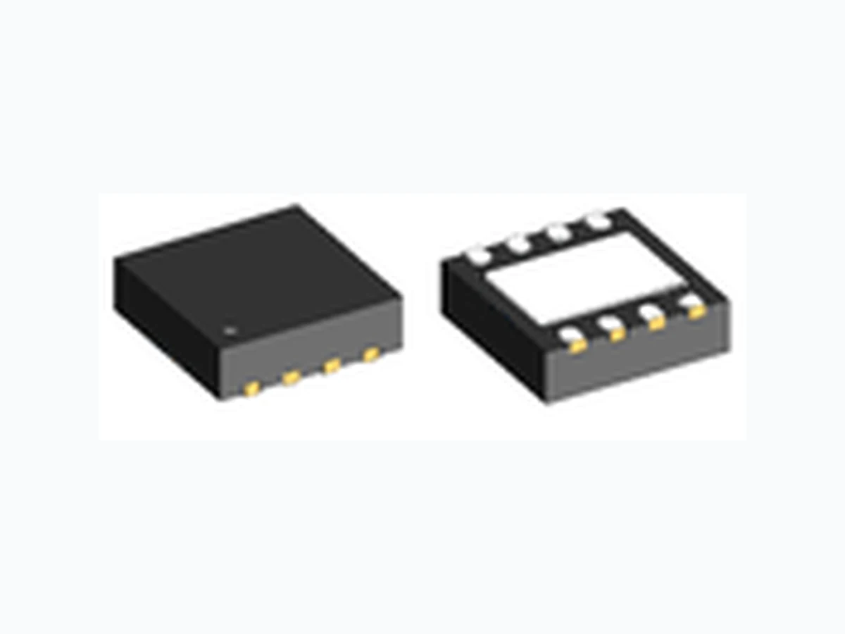
LC101N is a current control IC that uses a low-saturated PNP bipolar transistor in the power block. The saturation voltage of the saturated condition is small and can be designed with minimal losses in the case of driving with a constant current source. The constant current value is set up by the resistor connected between the FB terminal and the LO pin, and you can drive the LED in the constant current condition. LC101N is available in an 8-pin DFN package for surface mounting.
Features
- Maximum current is 150 mA
- Low input-output voltage difference design is achieved by low saturation voltage; VDIF(max.)=0.35 V (Io = 150 mA)
- Reference voltage of 200 mV reduces the sense resistor loss
- Optimal balance operation can be realise in parallel connection of multiple LED strings
- Protections Overcurrent Protection (OCP): Foldback Thermal Shutdown (TSD): Auto-restart
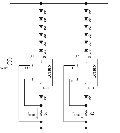
Typical Application
Data Sheet
Package
DFN 8
\*Not to scale
Electrical Characteristics
- Maximum input voltage: 35 V
- Maximum output current: 150 mA
- Reference voltage for the constant current control: 200 mV
- Power Dissipation: 1.3 W
Applications
- LED Lightings
- Back light system for LCD-Touch-panels,etc.
Page 2
CONTENTS
Description ------------------------------------------------------------------------------------------------------ 1
CONTENTS ---------------------------------------------------------------------------------------------------- 2
- Absolute Maximum Ratings ----------------------------------------------------------------------------- 3 2. Recommended Operating Conditions ----------------------------------------------------------------- 3 3. Electrical Characteristics -------------------------------------------------------------------------------- 3 4. Thermal Resistance --------------------------------------------------------------------------------------- 3 5. Derating Curve -------------------------------------------------------------------------------------------- 4 6. Block Diagram --------------------------------------------------------------------------------------------- 5
- Pin Configuration Definitions --------------------------------------------------------------------------- 5 8. Typical Application --------------------------------------------------------------------------------------- 6 9. External Dimensions -------------------------------------------------------------------------------------- 7 10. Marking Diagram ----------------------------------------------------------------------------------------- 7 11. Operational Description --------------------------------------------------------------------------------- 8 11.1 Basic operation --------------------------------------------------------------------------------------- 8
11.2 Power Supply----------------------------------------------------------------------------------------- 8 11.3 Current Balance Operation ----------------------------------------------------------------------- 8 11.4 Operable voltage of LC101N ---------------------------------------------------------------------- 9 11.5 Overcurrent Protection (OCP) ------------------------------------------------------------------- 9 11.6 Thermal Shutdown (TSD) ------------------------------------------------------------------------- 9 12. Design Notes ------------------------------------------------------------------------------------------------ 9 12.1 External Components ------------------------------------------------------------------------------ 9
12.1.1 LED current setup resistor, R1 ------------------------------------------------------------- 9 12.2 Pattern Layout ------------------------------------------------------------------------------------- 10 12.2.1 PCB Trace Layout and Component Placement --------------------------------------- 10 12.2.2 Pattern Layout Example ------------------------------------------------------------------- 10 12.2.3 Land Pattern Example --------------------------------------------------------------------- 11 13. Typical Performance Curves -------------------------------------------------------------------------- 11 14. Packing Specifications ---------------------------------------------------------------------------------- 12
14.1 Emboss and Carrier Tape Specification ------------------------------------------------------ 12 14.2 Reel Specifications -------------------------------------------------------------------------------- 13 15. Recommended Reflow Temperature Profile ------------------------------------------------------- 14
IMPORTANT NOTES ------------------------------------------------------------------------------------- 15
Page 3
1. Absolute Maximum Ratings
- Unless otherwise specified TA = 25 °C, the LO pin is reference voltage level.
| Parameter | Symbol | Rating | Units | Notes |
|---|---|---|---|---|
| DC input voltage | V IN | 35 | V | |
| LED pin voltage | V LED | V IN | V | |
| FB pin voltage | V FB | 5 | V | |
| Allowable Power Dissipation | P D | 1.3 | W | Reference layout pattern mounting on the FR4 double-sided PCB. Refer to Section 12.2.2. |
| Junction Temperature | T j | − 40 to 125 | °C | |
| Storage Temperature | T stg | − 40to 80 | °C |
\* When the junction temperature of the IC becomes 110 °C (min.) or more, the thermal shutdown (TSD) activates.
2. Recommended Operating Conditions
- Unless otherwise specified TA = 25 °C, the LO pin is reference voltage level.
| Parameter | Symbol | Min. | Max. | Units | Notes |
|---|---|---|---|---|---|
| IN-LO Voltage | V IN | 2.4 | * | V | |
| Output Current | I LED | 15 | 150* | mA | |
| Operating Ambient Temperature | T OP | − 20 | + 80 | °C |
\* Since the between VIN and ILED has following relationship, the value of VIN is different by condition. Allowable power dissipation, PD is calculated by Figure 5-1.
PD(MAX) = (VIN − VLED) × ILED(MAX)
(1)
3. Electrical Characteristics
- Unless otherwise specified TA = 25 °C, the LO pin is reference voltage level.
| Parameter | Symbol | Conditions | Min. | Typ. | Max. | Units |
|---|---|---|---|---|---|---|
| Reference Voltage | V FB | V = 4 V, I = 15 mA IN LED | 0.194 | 0.200 | 0.206 | V |
| Reference Voltage Temperature Coefficient (1) | ΔV FB/TA | T = 25 °C to 100 °C j | -0.02 | mV/°C | ||
| Voltage Difference between Input and Output (2) | ΔV DIF | I ≤ 50 mA LED | 0.18 | V | ||
| I ≤ 150 mA LED | 0.35 | V | ||||
| Overcurrent protection threshold Current | I S1 | V = 4V, V = 90 % IN LED | 160 | mA | ||
| Thermal Shutdown Temperature(1) | T SD | 110 | 130 | °C |
(1) Design assurance. (2) The saturation voltage between the IN pin and the LED pin.
4. Thermal Resistance
- Unless otherwise specified TA = 25 °C, the LO pin is reference voltage level.
| Parameter | Symbol | Rating | Units | Notes |
|---|---|---|---|---|
| Junction to Ambient Thermal Resistance | θ j-A | 65 | °C/W | |
| Junction to Case Thermal Resistance | θ j-TOP | 27 | °C/W | Marking surface |
Page 4
5. Derating Curve
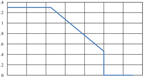
Figure 5-1 shows the thermal derating curve that the IC is mounted on the pattern layout example of Section 12.2.2, and is calculated based on the junction temperature 110 ° C. When the junction temperature becomes 110 ° C or more, thermal shutdown might be activated.
1.4
1.2
0.8
0.6
0.4
0.2
-20 0 20 40 60 80 100 120
Ambient temperature, TA (°C)
Figure 5-1 Thermal Derating Curve
- Junction Temperature Calculation The junction tenperature,Tj is calucrated by using Equation (2)
Tj = PD × θj-TOP+TTOP (°C)
(2)
where, θj-TOP = 27 °C/W and TTOP is the measurement temperature of marking surface.
Page 5
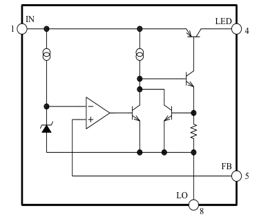
6. Block Diagram
7. Pin Configuration Definitions
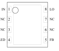
| Pin | Name | Descriptions |
|---|---|---|
| 1 | IN | Constant current source input |
| 2 | NC | Not connected |
| 3 | NC | Not connected |
| 4 | LED | Output pin to LED |
| 5 | FB | LED current detection signal input (positive side) |
| 6 | NC | Not connected |
| 7 | NC | Not connected |
| 8 | LO | LED current detection signal input (negative side) |
Page 6
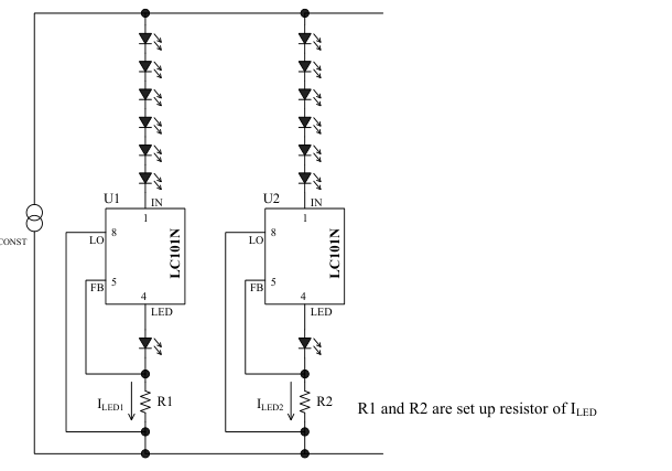
- Typical Application
Page 7
- External Dimensions
- DFN8
<Top View>
<Bottom View>
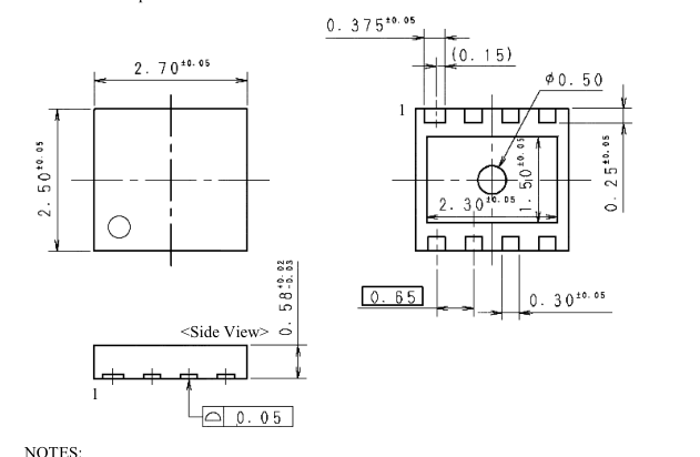
- Dimension is in millimeters
- Pb-free. Device composition compliant with the RoHS directive
- Width of 1 pin is 0.375 mm, the others are 0.3mm
- In order to release temperrature The heat slug of the back surface should heat dissipation to the pattern of PCB.
- Marking Diagram
Abbreviated product number (LC101N)
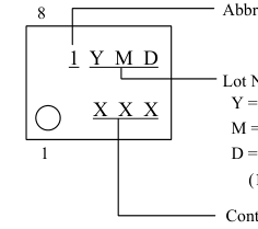
Lot Number Y = Last Digit of Year (0~9) M = Month (1~9, O, N or D) D = Period of days (1~9 or A~Z without B, I, O and Q)
Control Number
Page 8
11. Operational Description
11.1 Basic operation
The current control of the LC101N is quite simple. The both end voltage of the setup resistor R1 which is connected between the FB terminal and the LO pin. So that it becomes constant, the emitter-collector voltage of the internal PNP-transistor is linear-controlled by the error amplifier. Figure 11-1 shows the basic circuit of LC101N.
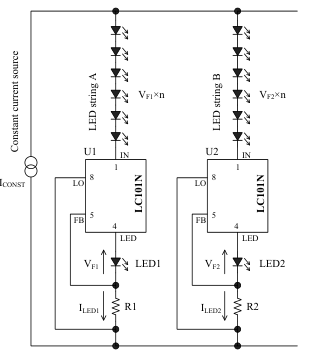
Figure 11-1 LC101N basic circuit
LED current, ILED is calculated by Equation (3).
(3)
From Equation (3), the setup resistor, R1 is calculated by Equation (4).
(4)
The reference voltage, VFB for the constant current control is 200 mV. The both end voltage of R1 is controlled to become equal to VFB.
The loss of R1, PR1 is calculated by Equation (5).
(5)
Table 11-1 shows the calculation result of relationship of ILED, R1, and PR1.
Table 11-1 The loss of R1, PR1
| I (mA) LED | R1 (Ω) | P (mW) R1 |
| 50 | 4 | 10 |
| 100 | 2 | 20 |
| 150 | 1.33 | 30 |
In addition, the loss of the IC, PD is calculated by Equation (6).
(6)
where, VIN is the voltage between the IN pin and the LO pin, and VLED is the voltage between the LED pin and LO pin.
11.2 Power Supply
The power supply should be use the constant-current source. If the constant-voltage source is used, the voltage difference between input and output that does not require for LED becomes the loss of the IC. Though it will operate with the constant-voltage source, if the input-output voltage difference becomes larger than necessary, and all of surplus will be loss in this IC The ability of power supply, PIN is required to satisfy following equation.
(7)
where, N is number of LED in series, VF is forward voltage of LED, and ICONST is the constant current of power supply.
For example, LED current is set to 50 mA in Figure 11-1. The constant current of power supply, ICONST, is set fewer than the total current value of LED-strings A and B (100mA), because the drooping characteristic of constant-current source is considered. In this case, ICONST is set 95 mA. If VF = 3V and n = 7, PIN becomes as follows:
11.3 Current Balance Operation
If All LEDs have same VF, and the same current flows to LED-string A and B, the power loss of IC becomes minimum because the circuit is controlled by the constant-current source, ICONST and the internal transistor is a saturated condition. However, the complete equilibrium state is impossible by characteristic variations of VF. If each VF2 of LED string B is smaller than VF1 of LED string A by 0.1 V.
Page 9
. In this case,
is applied to between the IN pin and the LED pin of LC101N. Since the LED string B current, ILED2, is controlled to constant by R2, the loss of LC101N of LED string B side is following value, and is enough acceptable value.
If it is operated in the constant current source, the voltage applied to the LED string, it becomes the minimum requirement value of the LED-string with the highest VF. When the constant current source is used, the necessary voltage for LED string with the highest total VF is supplied. Thus, LC101N reduces the current concentration by VF fluctuation and, the brightness unevenness.
11.4 Operable voltage of LC101N
Operating conditions of LC101N are as follows:
- The minimum difference voltage between the IN pin and thr LED pin is higher than the ΔVDIF.
- The voltage of the IN pin is higher than 2.4V(min.) against the LO pin. One LED is added to the LED pin and setup resistor
as shown in Figure 11-1 in order to have enough voltage between the IN pin and the LO pin.
11.5 Overcurrent Protection (OCP)
The LC101N have the fold-back characteristics in overcurrent protection (OCP) as shown in Figure 13-2. The short circuit current does not return to completely 0 A, because start-up characteristics is considered. Thus, be careful to heat generation. When OCP is activated, the LED pin voltage decreases. Then, the difference voltage between input and output is increased, and the temperature of IC increases. In this case, Thermal shutdown might activate (refer to Section 11.6).
11.6 Thermal Shutdown (TSD)
LC101N has the Thermal Shutdown (TSD). The junction temperature of the IC chip, Tj, is detected. When Tj is increase to TSD = 130 °C (typ.), the drive current of the internal PNP transistor is limited. Since the minimum activation temperature of the TSD is 110 °C, Tj should be set less than 110 °C in thermal design.
TSD does not have hysteresis. When Tj decreases to TSD or less, the IC returns to normal operation automatically. When TSD is activated under the overcurrent condition, following condition is repeated and output voltage waveform, VLED, becomes intermittent oscillation (refer to Figure 13-4). Overcurrent condition −> VLED decreases −> ILED decreases −> junction temperature Tj decreases −> automatically restart −> Overcurrent condition….
- Notice of TSD The purpose of the TSD is the protection of IC from
temporary heat generation. TSD does not guarantee the operation including reliabilities under the continuous heat generation conditions, such as short circuit for a long time. Since the temperature of LC101N which is connected to the LED depends on the mounting location (distance) and the wiring method, TSD might be activated by the thermal of LEDs.
12. Design Notes
12.1 External Components
All components are required for matching to the condition of use.
12.1.1 LED current setup resistor, R1
Reference voltage of LC101N, VFB, controls the LED current, is 200 mV. The IC controls so that the VFB and both end voltage of setup resistor R1 is equal. Because the VFB is low voltage, the resistor should not be selected wirewound resistors to prevent malfunction in transient state including start/stop operation. In addition, lead of the resistor of through hole type should be short to reduce the back electromotive voltage by the parasitic inductance. R1 is recommended surface device, and should be as close to LC101N as possible. If the problem occurs at the open-short test of resistor, please considering the series-parallel connection of the resistor. R1 setup is as shown in Table 11-1.
Page 10
12.2 Pattern Layout
12.2.1 PCB Trace Layout and Component
Placement
- Setup resistance, R1, should be as close to the FB pin and the LO pin as possible as shown in Figure 12-1.
- The layout between the FB pin and the LED string should be avoided to parallel with switching trace. Noise is superimposed to the FB pin by induction, the LC101N might be malfunction.
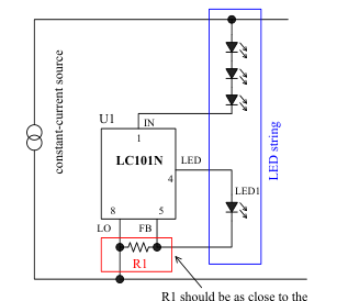
FB pin and the LO pin.
Figure 12-1 Important locations of the pattern layout
12.2.2 Pattern Layout Example
Figure 12-2 shows the pattern layout example, and Table 12-1 shows this PCB information.
Table 12-1 PCB information of pattern layout example
| Items | Information |
| PCB type | double-sided |
| Size(Outline) | 40 mm × 40 mm |
| Substrate thickness | t = 1.6 mm |
| Copper foil thickness | 35 μm |
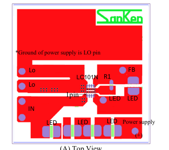
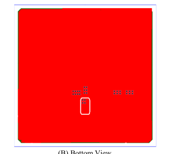
(B) Bottom View
Figure 12-2 Pattern layout example
Page 11
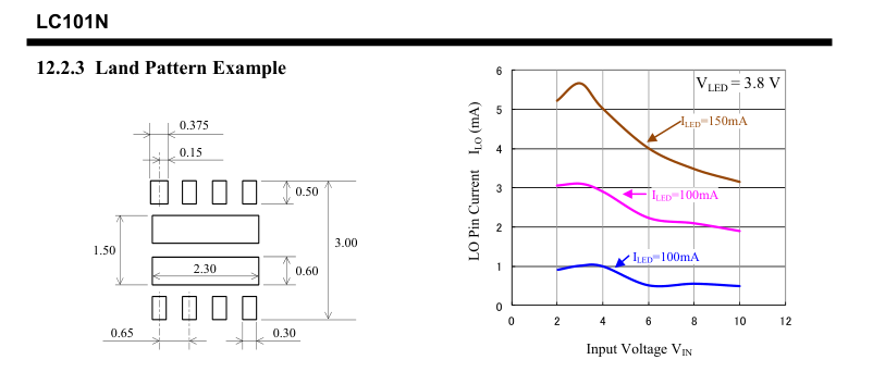
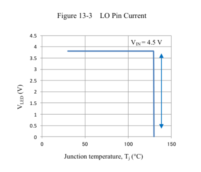
Figure 12-3 Land pattern example (not to scale)
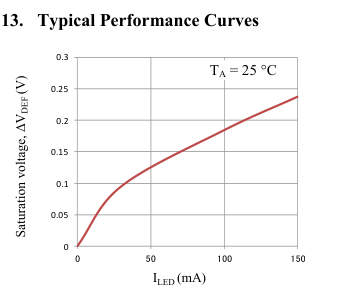
Figure 13-4 Thermal shutdown characteristic
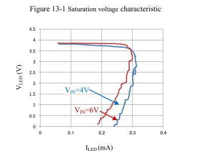
Figure 13-2 Overcurrent characteristic
Page 12
14. Packing Specifications
14.1 Emboss and Carrier Tape Specification
The direction of tape drawer
Empty seal part

The direction of tape drawer
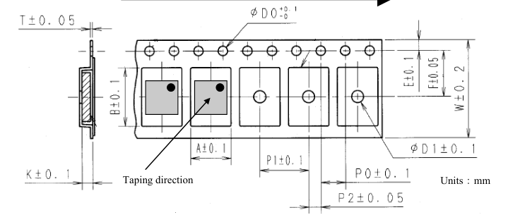

Figure 14-1 Emboss and carrier tape dimensions
Page 13
14.2 Reel Specifications
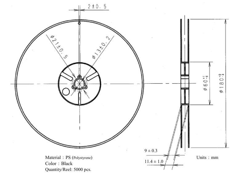
Figure 14-2 Reel dimensions
Page 14
15. Recommended Reflow Temperature Profile
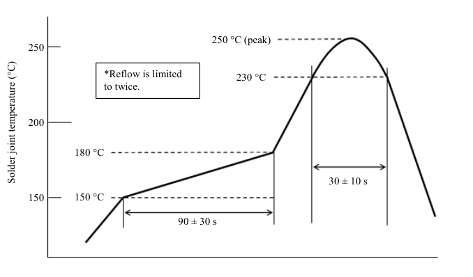
Figure 15-1 Recommended reflow temperature profile
Page 15
IMPORTANT NOTES
- All data, illustrations, graphs, tables and any other information included in this document as to Sanken’s products listed herein (the “Sanken Products”) are current as of the date this document is issued. All contents in this document are subject to any change without notice due to improvement, etc. Please make sure that the contents set forth in this document reflect the latest revisions before use.
- The Sanken Products are intended for use as components of general purpose electronic equipment or apparatus (such as home appliances, office equipment, telecommunication equipment, measuring equipment, etc.). Prior to use of the Sanken Products, please put your signature, or affix your name and seal, on the specification documents of the Sanken Products and return them to Sanken. If considering use of the Sanken Products for any applications that require higher reliability (transportation equipment and its control systems, traffic signal control systems or equipment, disaster/crime alarm systems, various safety devices, etc.), you must contact a Sanken sales representative to discuss the suitability of such use and put your signature, or affix your name and seal, on the specification documents of the Sanken Products and return them to Sanken, prior to the use of the Sanken Products. Any use of the Sanken Products without the prior written consent of Sanken in any applications where extremely high reliability is required (aerospace equipment, nuclear power control systems, life support systems, etc.) is strictly prohibited.
- In the event of using the Sanken Products by either (i) combining other products or materials therewith or (ii) physically, chemically or otherwise processing or treating the same, you must duly consider all possible risks that may result from all such uses in advance and proceed therewith at your own responsibility.
- Although Sanken is making efforts to enhance the quality and reliability of its products, it is impossible to completely avoid the occurrence of any failure or defect in semiconductor products at a certain rate. You must take, at your own responsibility, preventative measures including using a sufficient safety design and confirming safety of any equipment or systems in/for which the Sanken Products are used, upon due consideration of a failure occurrence rate or derating, etc., in order not to cause any human injury or death, fire accident or social harm which may result from any failure or malfunction of the Sanken Products. Please refer to the relevant specification documents and Sanken’s official website in relation to derating.
- No anti-radioactive ray design has been adopted for the Sanken Products.
- No contents in this document can be transcribed or copied without Sanken’s prior written consent.
- The circuit constant, operation examples, circuit examples, pattern layout examples, design examples, recommended examples and evaluation results based thereon, etc., described in this document are presented for the sole purpose of reference of use of the Sanken Products and Sanken assumes no responsibility whatsoever for any and all damages and losses that may be suffered by you, users or any third party, or any possible infringement of any and all property rights including intellectual property rights and any other rights of you, users or any third party, resulting from the foregoing.
- All technical information described in this document (the “Technical Information”) is presented for the sole purpose of reference of use of the Sanken Products and no license, express, implied or otherwise, is granted hereby under any intellectual property rights or any other rights of Sanken.
- Unless otherwise agreed in writing between Sanken and you, Sanken makes no warranty of any kind, whether express or implied, as to the quality of the Sanken Products (including the merchantability, or fitness for a particular purpose or a special environment thereof), and any information contained in this document (including its accuracy, usefulness, or reliability).
- In the event of using the Sanken Products, you must use the same after carefully examining all applicable environmental laws and regulations that regulate the inclusion or use of any particular controlled substances, including, but not limited to, the EU RoHS Directive, so as to be in strict compliance with such applicable laws and regulations.
- You must not use the Sanken Products or the Technical Information for the purpose of any military applications or use, including but not limited to the development of weapons of mass destruction. In the event of exporting the Sanken Products or the Technical Information, or providing them for non-residents, you must comply with all applicable export control laws and regulations in each country including the U.S. Export Administration Regulations (EAR) and the Foreign Exchange and Foreign Trade Act of Japan, and follow the procedures required by such applicable laws and regulations.
- Sanken assumes no responsibility for any troubles, which may occur during the transportation of the Sanken Products including the falling thereof, out of Sanken’s distribution network.
- Although Sanken has prepared this document with its due care to pursue the accuracy thereof, Sanken does not warrant that it is error free and Sanken assumes no liability whatsoever for any and all damages and losses which may be suffered by you resulting from any possible errors or omissions in connection with the contents included herein.
- Please refer to the relevant specification documents in relation to particular precautions when using the Sanken Products, and refer to our official website in relation to general instructions and directions for using the Sanken Products.