
DATASHEET SEARCH SITE
Document overview
- Manufacturer or author: Provided By www.digicamel.com(FREE DATASHEET DOWNLOAD SITE)
- PDF pages: 4
Technical content
Features
Applications
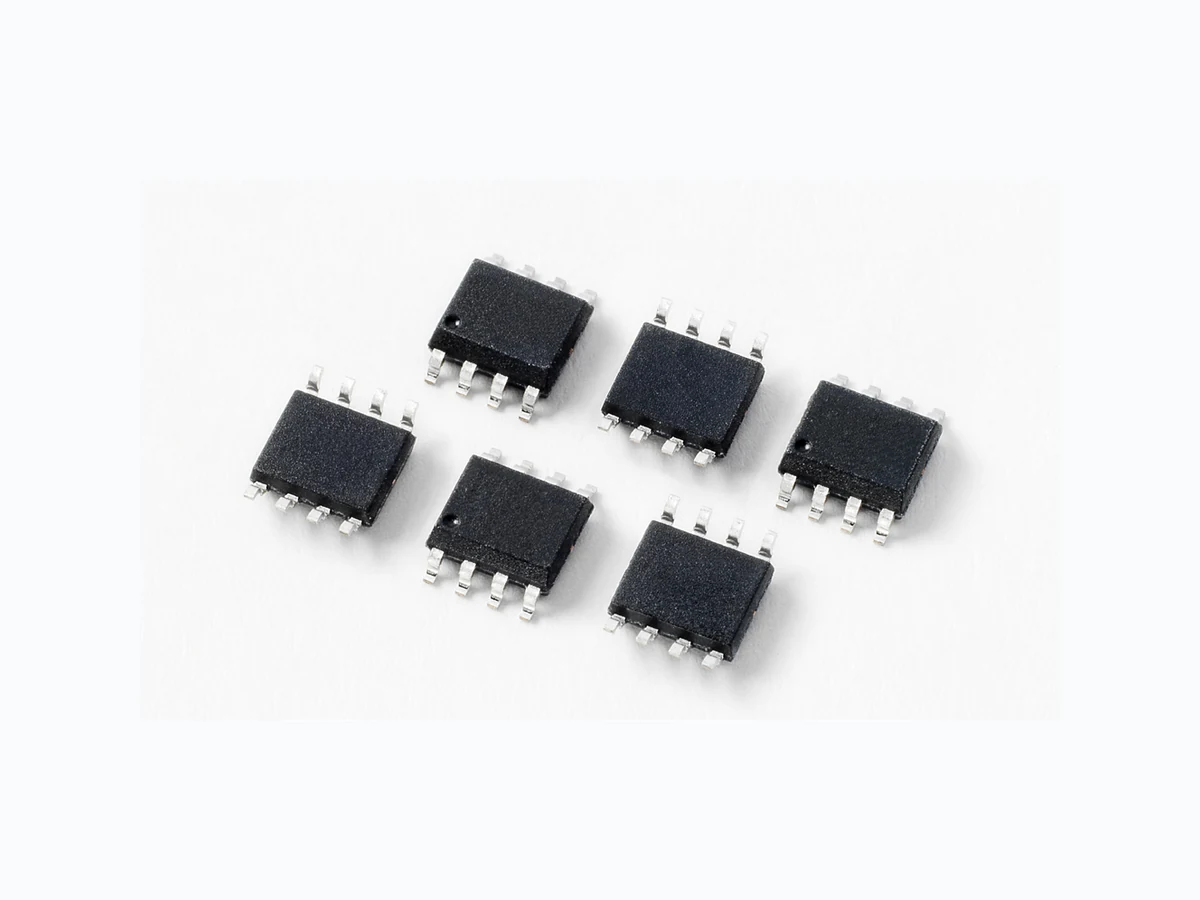
This LC03-3.3 series provides overvoltage protection for applications such as 10/100/1000 BaseT Ethernet and T3/E3 interfaces. This new protector combines the TVS diode element with a diode rectifier bridge to provide both longitudinal and differential protection in one package. This design results in a capacitive loading characteristic that is log-linear with respect to the signal voltage across the device. This reduces intermodulation (IM) distortion caused by a typical solid-state protection solution. The application schematic provides the connection information and the LC03-3.3 is rated for GR-1089, intra-building transient immunity requirements for telecommunication installations. Pinout Functional Block Diagram
- Lightning Protection, IEC 61000-4-5 2nd edition, 150A (t p=8/20µs)
- EFT , IEC 61000-4-4, 40A (tp=5/50ns)
- Low insertion loss, log- linear capacitance
- Low clamping voltage
- SOIC-8 surface mount package (JEDEC MS-012)
- UL 94V-0 epoxy molding
- RoHS and Lead-free compliant
- Moisture Sensitivity Level (MSL -1)
- T1/E1 Line cards
- T3/E3 and DS3 Interfaces
- STS-1 Interfaces
- 10/100/1000 BaseT Ethernet SOIC-8 (Top View) Pin 1 and 8 Pin 4 and 5 Pin 2, 3, 6, and 7 Line out Line outLine in Line in Life Support Note: Not Intended for Use in Life Support or Life Saving Applications The products shown herein are not designed for use in life sustaining or life saving applications unless otherwise expressly indicated. Application Example This schematic shows a high-speed data interface protection solution. The LC03-3.3BTG is compatible with the intra-building surge requirements of Telcordia’s GR- 1089-CORE, and the Basic Level Recommendations of ITU K.20 and K.21 . The TeleLink fuse provides overcurrent protection for the long term 50/60 Hz power fault events. TeleLink (0461 1.25) LC03-3.3BTG to chipset (Ethernet PHY, T3/E3 PHY, etc.) RoHS Pb GREENLC03-3.3 Series 3.3V 150A Diode Array Additional Information Datasheet SamplesResources
© 2017 Littelfuse, Inc. Specifications are subject to change without notice. Revised: 02/23/17 TVS Diode Arrays (SPA® Diodes) Lightning Surge Protection - LC03-3.3 Series SP03A-3.3 Absolute Maximum Ratings Parameter Rating Units Peak Pulse Current (8/20µs) 150 A Peak Pulse Power (8/20µs) 3300 W IEC 61000-4-2, Direct Discharge, (Level 4) 30 kV IEC 61000-4-2, Air Discharge, (Level 4) 30 kV IEC 61000-4-5 (8/20µs) 150 A Telcordia GR 1089 (Intra-Building) (2/10µs) 100 A ITU K.20 (5/310µs) 40 A Electrical Characteristics (TOP = 25°C) Thermal Information Parameter Rating Units Operating Temperature Range –40 to 125 °C Storage Temperature Range –55 to 150 °C Maximum Junction Temperature 150 °C Maximum Lead Temperature (Soldering 20-40s) (SOIC - Lead Tips Only) 260 °C Parameter Symbol Test Conditions Min Typ Max Units Reverse Stand-Off Voltage VRWM IT≤1µA - - 3.3 V Reverse Breakdown Voltage VBR IT= 2µA 3.3 - - V Snap Back Voltage VSB IT= 50mA 3.3 - - V Reverse Leakage Current IR VRWM= 3.3V , T= 25°C - - 1 µA Clamping Voltage, Line-Ground VC IPP= 50A, tp=8/20 µs - - 13 V Clamping Voltage, Line-Ground VC IPP= 100A, tp=8/20 µs - - 17 V Dynamic Resistance, Line-Ground RDYN (VC2-VC1)/(IPP2-IPP1) - 0.15 - W Clamping Voltage, Line-Line VC IPP= 50A, tp=8/20 µs - - 15 V Clamping Voltage, Line-Line VC IPP= 100A, tp=8/20 µs - - 20 V Dynamic Resistance , Line-Line RDYN (VC2-VC1)/(IPP2-IPP1) - 0.25 - W Junction Capacitance Cj Between I/O Pins and Ground VR=0V , f= 1MHz - 9 12 pF Between I/O Pins VR=0V , f= 1MHz - 4.5 6 pF CAUTION: Stresses above those listed in “Absolute Maximum Ratings” may cause permanent damage to the device. This is a stress only rating and operation of the device at these or any other conditions above those indicated in the operational sections of this specification is not implied. Figure 2: Current Derating CurveFigure 1: Non-repetitive Peak Pulse Current vs. Pulse Time Pulse decay time (µs) 100 1000 11 01 00 1000 Peak Pulse Cur rent (A) Per centage of Rat ed Cur rent (%I Ambient Temperature (C) 100 120 02 04 06 08 01 00 1201 40 160
© 2017 Littelfuse, Inc. Specifications are subject to change without notice. Revised: 02/23/17 TVS Diode Arrays (SPA® Diodes) Lightning Surge Protection - LC03-3.3 Series SP03A-3.3 Part Numbering System Product Characteristics
Ordering Information
Part Number Package Marking Min. Order Qty. LC03-3.3BTG SOIC-8 LC03-3.3 2500 Lead Plating Matte Tin Lead Material Copper Alloy Lead Coplanarity 0.004 inches (0.102mm) Substitute Material Silicon Body Material Molded Epoxy Flammability UL 94 V-0 LC03 3.3 B T G Series Working Voltage Package T= Tape & Reel G= Green B = SOIC Part Marking System Package Dimensions — Mechanical Drawings and Recommended Solder Pad Outline Package SOIC-8 Pins 8 JEDEC MS-012 Millimetres Inches Min Max Min Max A 1 .35 1 .75 0.053 0.069 A1 0.10 0.25 0.004 0.010 A2 1 .25 1 .65 0.050 0.065 B 0.31 0.51 0.012 0.020 c 0.17 0.25 0.007 0.010 D 4.80 5.00 0.189 0.197 E 5.80 6.20 0.228 0.244 E1 3.80 4.00 0.150 0.157 e 1 .27 BSC 0.050 BSC L 0.40 1 .27 0.016 0.050 o Recommended Soldering Pad Outline (Reference Only) FL First Line: Part number Second Line: Date code FLLC03-3.3 XXXXXXXX Notes : 1 . All dimensions are in millimeters 2. Dimensions include solder plating. 3. Dimensions are exclusive of mold flash & metal burr. 4. Blo is facing up for mold and facing down for trim/form, i.e. reverse trim/form. 5. Package surface matte finish VDI 11-13. Embossed Carrier T ape & Reel Specification — SOIC Package Millimetres Inches Min Max Min Max E 1 .65 1 .85 0.065 0.073 F 5.4 5.6 0.213 0.22 P2 1 .95 2.05 0.077 0.081 D 1. 5 1. 6 0.059 0.063 D1 1 .50 Min 0.059 Min P0 3.9 4.1 0.154 0.161 10P0 40.0 ± 0.20 1 .57 4 ± 0.008 W 11. 9 12.1 0.468 0.476 P 7. 9 8.1 0.311 0.319 A0 6.3 6.5 0.248 0.256 B0 5.1 5.3 0.2 0.209 K0 2 2.2 0.079 0.087 t 0.30 ± 0.05 0.012 ± 0.002 User Feeding Direction Pin 1 Location Disclaimer Notice - Information furnished is believed to be accurate and reliable. However, users should independently evaluate the suitability of and test each product selected for their own applications. Littelfuse products are not designed for, and may not be used in, all applications. Read complete Disclaimer Notice at www.littelfuse.com/disclaimer-electronics.