Download PDF
DATASHEET SEARCH SITE
Document overview
- PDF pages: 4
Technical content
Page 1
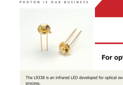
For optical switches
The L9338 is an infrared LED developed for optical switches and is available at a low cost due to the improved manufacturing
Features
Applications
High reliability
Optical switches
Low price
Absolute maximum ratings (Ta=25 °C, unless otherwise noted)
| Parameter | Symbol | Condition | Value | Unit |
|---|---|---|---|---|
| Reverse voltage | VR | 5 | V | |
| Forward current | IF | 80 | mA | |
| Forward current reduction rate | - | Ta>25 °C | 1.1 | mA/°C |
| Pulse forward current | IFP | Pulse width=10 μs Duty ratio=1% | 1.0 | A |
| Pulse forward current reduction rate | - | Ta>25 °C | 13 | mA/°C |
| Power dissipation | P | 150 | mW | |
| Operating temperature | Topr | -30 to +85 | °C | |
| Storage temperature | Tstg | -40 to +100 *1 | °C |
\*1: Guaranteed to resist temperature cycle test of up to 5 cycles Note: Exceeding the absolute maximum ratings even momentarily may cause a drop in product quality. Always be sure to use the product within the absolute maximum ratings.
Electrical and optical characteristics (Ta=25 °C)
| Parameter | Symbol | Condition | Min. | Typ. | Max. | Unit |
|---|---|---|---|---|---|---|
| Peak emission wavelength | λp | IF=50 mA | 920 | 945 | 970 | nm |
| Spectral half width | ∆λ | IF=50 mA | - | 60 | - | nm |
| Forward voltage | VF | IF=50 mA | - | 1.34 | 1.42 | V |
| Pulse forward voltage | VFP | IF=1 A | - | 3.1 | 3.8 | V |
| Reverse current | IR | VR=5 V | - | - | 5 | μA |
| Radiant fl ux | ɸe | IF=50 mA | 10 | 15 | - | mW |
| Cutoff frequency*2 | fc | IF=50 mA ± 4 mAp-p | 0.1 | 0.3 | - | MHz |
\*2: Frequency at which the optical output drops by 3 dB from that at 10 kHz
www.hamamatsu.com
Page 2
Emission spectrum
(Typ. Ta=25 °C, IF=50 mA)
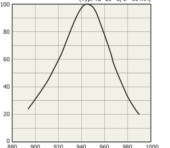
Wavelength (nm)
KLEDB0255EA
Forward current vs. forward voltage
(Typ. Ta=25 °C, tw=100 μs, 1%)
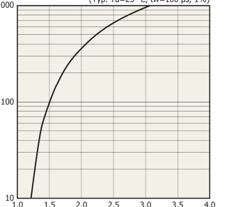
Forward voltage (V)
KLEDB0257EB
Radiant flux vs. forward current
(Typ. Ta=25 °C, tw=100 μs, 1%)
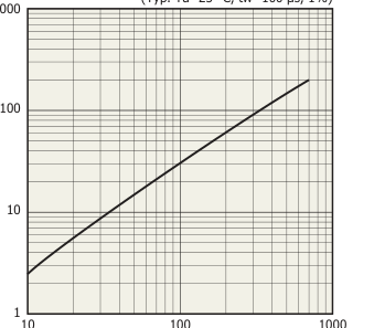
Forward current (mA)
KLEDB0256EB
Directivity
(Typ. Ta=25 °C)
20° 10°
10° 20°
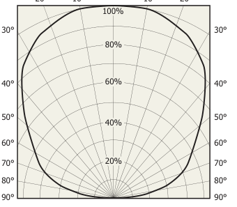
Relative radiant output (%)
KLEDB0258EA
Page 3
Radiant output vs. ambient temperature
(Typ. IF=50 mA)
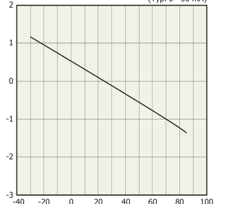
Ambient temperature (°C)
KLEDB0259EA
Allowable forward current vs. duty ratio
(Ta=25 °C)
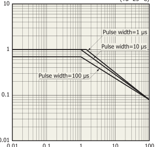
Duty ratio (%)
KLEDB0038EB
Allowable forward current vs. ambient temperature
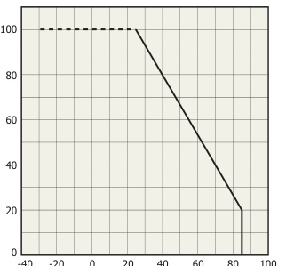
Ambient temperature (°C)
KLEDB0254EB
Page 4
Dimensional outline (unit: mm)
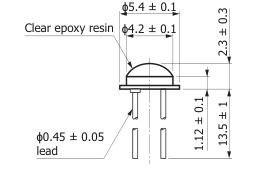
ϕ2.54 ± 0.2
Common to case
KLEDA0081EA
Related information
www.hamamatsu.com/sp/ssd/doc_en.html
Precautions
∙ Disclaimer ∙ Metal, ceramic, plastic products
Information described in this material is current as of November, 2015. Product specifications are subject to change without prior notice due to improvements or other reasons. This document has been carefully prepared and the information contained is believed to be accurate. In rare cases, however, there may be inaccuracies such as text errors. Before using these products, always contact us for the delivery specification sheet to check the latest specifications. The product warranty is valid for one year after delivery and is limited to product repair or replacement for defects discovered and reported to us within that one year period. However, even if within the warranty period we accept absolutely no liability for any loss caused by natural disasters or improper product use.
Copying or reprinting the contents described in this material in whole or in part is prohibited without our prior permission.