

 Download PDF
DATASHEET SEARCH SITE
Document overview
- PDF pages: 4
Technical content
Page 1
130 kV

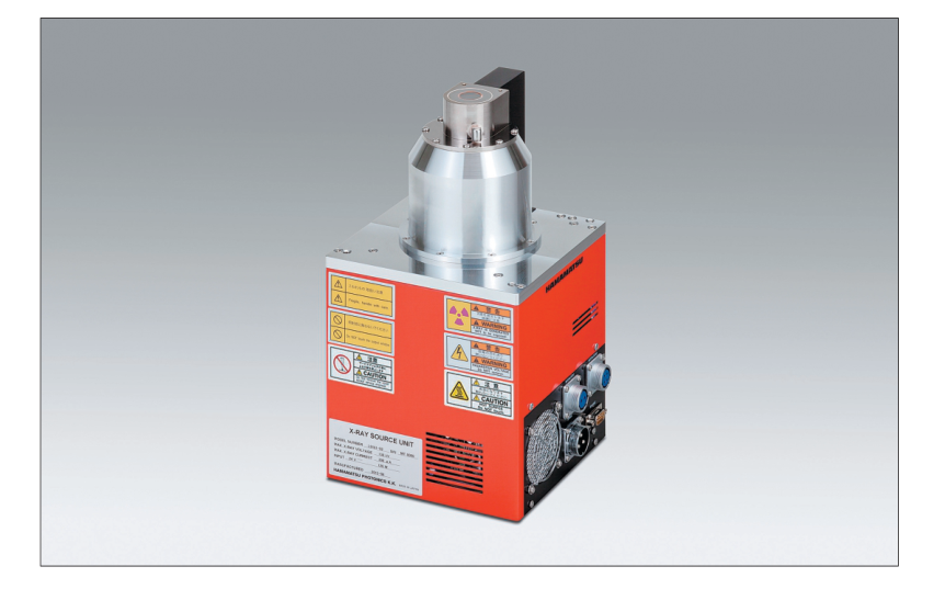
MICROFOCUS X-RAY SOURCE
L9181-02
FEATURES
GFocal spot size: 5 µm (at 4 W)
The focal spot of 5 µm of the sealed type X-ray tube offers sharp and clear X-ray images even at a high magnification.
GNo high voltage cable connection required
High voltage power supply is integrated.
GExternal control via RS-232C interface GHigh power: Maximum output 39 W
APPLICATIONS
GNon-destructive inspection GX-ray CT
[Applicable objects]
- Electronic component
- Printed circuit board
- Plastic component
- Metal component
Page 2
SPECIFICATIONS
GENERAL
| Parameter | Description / Value | Unit | |
|---|---|---|---|
| X-ray tube voltage setting range | 0 to 130 | kV | |
| X-ray tube current setting range | 0 to 300 | µA | |
| X-ray tube voltage operational range 1 | 40 to 130 | kV | |
| X-ray tube current operational range 1 | 10 to 300 | µA | |
| Maximum output | Small focus mode | 8 | W |
| Middle focus mode | 16 | ||
| Large focus mode | 39 | ||
| X-ray focal spot size (Nominal value) | Small focus mode | 8 (5 µm at 4 W) | µm |
| Middle focus mode | 20 | ||
| Large focus mode | 40 | ||
| X-ray output window material / Thickness | Beryllium/0.2 | mm | |
| X-ray beam angle 2 | Approx. 45 | degree | |
| Focus to object distance (FOD) | Approx. 13 | mm | |
| Terget material | Tungsten | — | |
| Weight 3 | Approx. 10.5 | kg | |
| Communication method | Interface: RS-232C (9-pin D-sub connector) | — | |
| RATINGS | |||
| Parameter | Description / Value | Unit | |
| Input voltage (DC) | +24 (+2.4, -0) | V | |
| Power consumption | Less than 120 | W | |
| Read output | Continuous rating | — | |
| Operating ambient temperature | +10 to +40 | °C | |
| Storage ambient temperature | 0 to +50 | °C | |
| Operating and storage humidity | 20 to 85 (No condensation) | % | |
| REGULATION AND STANDARD | |||
| Parameter | Description | Unit | |
| RoHS Directive | EN 50581 Category 9 | — | |
| EMC | Emission limits: CISPR 11 Group 1 Class A IEC/EN 61326-1 Immunity requirements: Table 2 | — | |
| CONTROL SOFTWARE 4 | |||
| Parameter | Description | Unit | |
| Applicable PC | PC / AT compatible | — | |
| Applicable OS | Windows® XP, 7 | — | |
| Interface | RS-232C interface | — | |
| NOTE: 1See the graph of the X-ray tube voltage / current operation range. 2Reference value: With 50 % of maximum X-ray emission. 3This weight includes the accessories of approx. 0.25 kg. 4The control software is provided as a sample software for the purpose of MFX operation. The performance of the software is not guaranteed. ! | |||
| PRECAUTIONS TO USE · This microfocus X-ray source generates X-rays harmful to the human body. Use sufficient caution when handling the equipment to avoid direct or inadvertent exposure to X-rays. Install the X-ray source or the X-ray tube unit in an X-ray shielded cabinet or room equipped with safety interlock functions to prevent accidental exposure to X-rays. | |||
| OPERATIONAL CAUTION · This microfocus X-ray source generates X-rays and must therefore be used only under the supervision of qualified personnel. · This microfocus X-ray source shall be used in compliance with health and safety regulations enforced in order to prevent health hazards problems due to ionizing radiation. | |||
Page 3
X-RAY TUBE VOLTAGE / CURRENT OPERATION RANGE
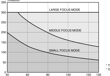
\* The X-ray tube voltage guaranteed range is 40 kV to 130 kV. \* Operation is not guaranteed when the tube current is below 10 µA.
TUBE VOLTAGE (kV)
DIMENSIONAL OUTLINE (Unit: mm)
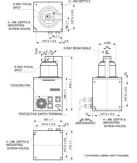
TXPRA0024EA
Page 4
RELATED PRODUCTS
X-RAY IMAGE INTENSIFIER DIGITAL CAMERA UNIT C7336-05/-52
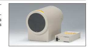
The C7336 series consist of a high resolution, high contrast 4-inch X-ray image in- tensifier (X-ray I.I.) and a 2.8 megapixel CMOS image sensor. The X-ray I.I. used has a fixed field-of-view of 100 mm diameter or a 4 inches/2 in- ches adjustable field-of-view and an input window made of thin aluminum which is excellent in X-ray transmission and causes less scattering of X-rays. These features allow real-time detection at X-ray energy levels from about 20 keV. The captured images can be transferred to PC directly by interface of IEEE1394b.
X-CUBE™ (COMPACT X-RAY CCD CAMERA) H8480, H8481, H8953
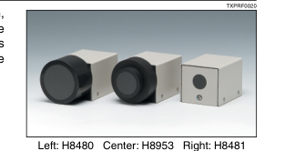
X-CUBEs are compact X-ray CCD camera designed for non-destructive inspection, which make X-ray imaging as easy as an ordinary CCD camera in handling. The H8480 and H8953 use a 2/3 type CCD coupled to large-diameter tapered FOPs which are coated with CsI. The H8481 uses a straight type FOP instead of the large FOP, achieving a high resolution of 20 Lp/mm.
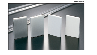
FOS (Fiber optic plate coated with X-ray scintillator)
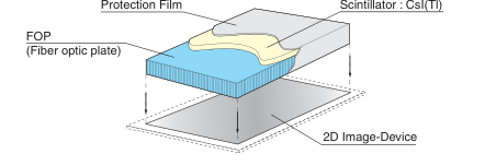
The FOS is an optical device for X-ray imaging, fabricated by coating an X-ray scintillator material over a fiber optic plate consisting of more than tens of million glass fibers each a few micrometers in diameter. The FOS provides higher sensitivity and resolution than currently used sensitized paper films and also allows real-time digital radiography when directly coupled to a commercially available CCD. The fiber optic plate used in the FOS has excellent X-ray absorption characteristics, so that X-rays penetrating the X-ray scintillator and directly entering the CCD are minimized to less than 1 %. This protects the CCD from the deterioration and in-
creased noise caused by X-ray irradiation, assuring a long service life and maintaining high image quality. Various sizes and shapes of FOS are available to meet your particular needs, including tapered FOP types.
IStructure
Windows® is a registered trademark of Microsoft Corporation in the United States and/or other countries. Other product and software names mentioned herein may be either registered trademarks or trademarks of their respective owners.
Subject to local technical requirements and regulations, availability of products included in this promotional material may vary. Please consult with our sales office. Information furnished by HAMAMATSU is believed to be reliable. However, no responsibility is assumed for possible inaccuracies or omissions. Specifications are subject to change without notice. No patent rights are granted to any of the circuits described herein. ©2015 Hamamatsu Photonics K.K.
HAMAMATSU PHOTONICS K.K.
www.hamamatsu.com
HAMAMATSU PHOTONICS K.K., Electron Tube Division 314-5, Shimokanzo, Iwata City, Shizuoka Pref., 438-0193, Japan, Telephone: (81)539/62-5248, Fax: (81)539/62-2205 U.S.A.: Hamamatsu Corporation: 360 Foothill Road, Bridgewater. N.J. 08807-0910, U.S.A., Telephone: (1)908-231-0960, Fax: (1)908-231-1218 E-mail: usa@hamamatsu.com Germany: Hamamatsu Photonics Deutschland GmbH: Arzbergerstr. 10, D-82211 Herrsching am Ammersee, Germany, Telephone: (49)8152-375-0, Fax: (49)8152-2658 E-mail: info@hamamatsu.de France: Hamamatsu Photonics France S.A.R.L.: 19, Rue du Saule Trapu, Parc du Moulin de Massy, 91882 Massy Cedex, France, Telephone: (33)1 69 53 71 00, Fax: (33)1 69 53 71 10 E-mail: infos@hamamatsu.fr
United Kingdom: Hamamatsu Photonics UK Limited: 2 Howard Court, 10 Tewin Road, Welwyn Garden City, Hertfordshire AL7 1BW, United Kingdom, Telephone: (44)1707-294888, Fax: (44)1707-325777 E-mail: info@hamamatsu.co.uk North Europe: Hamamatsu Photonics Norden AB: Torshamnsgatan 35 SE-164 40 Kista, Sweden, Telephone: (46)8-509-031-00, Fax: (46)8-509-031-01 E-mail: info@hamamatsu.se
TXPR1015E02
Italy: Hamamatsu Photonics Italia S.r.l.: Strada della Moia, 1 int. 6, 20020 Arese (Milano), Italy, Telephone: (39)02-93581733, Fax: (39)02-93581741 E-mail: info@hamamatsu.it China: Hamamatsu Photonics (China) Co., Ltd.: B1201 Jiaming Center, No.27 Dongsanhuan Beilu, Chaoyang District, Beijing 100020, China, Telephone: (86)10-6586-6006, Fax: (86)10-6586-2866 E-mail: hpc@hamamatsu.com.cn
NOV. 2015 IP