
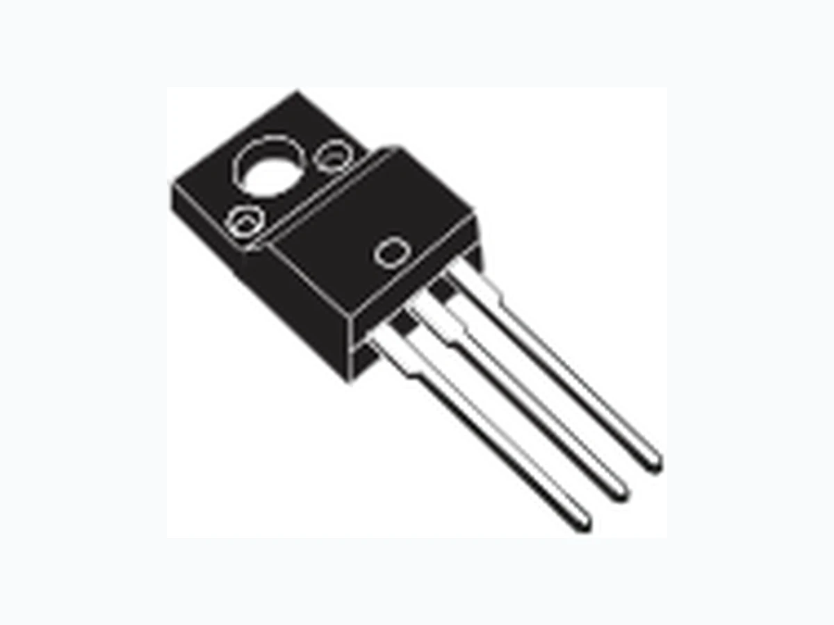
Datasheet - L78 - Positive voltage regulator ICs
Document overview
- Manufacturer or author: STMICROELECTRONICS
- PDF pages: 55
Technical content
Datasheet sections
- 1 Diagram
- 2 Pin configuration
- 3 Maximum ratings
- 4 Test circuits
- 5 Electrical characteristics
- 6 Application information
- 6.1 Design consideration
- 7 Typical performance
- 8 Package information
- 8.1 TO-220 (dual gauge) package information
- 8.2 TO-220 (single gauge) package information
- 8.3 TO-220FP type A package information
- 8.4 TO-220 (single/dual) packing information
- 8.5 DPAK package information
- 8.6 D²PAK (SMD 2L STD-ST) type A package information
- 8.7 D²PAK (ASE) type B package information
- 8.8 D²PAK and DPAK packing information
- 9 Ordering information
Features
- Output current up to 1.5 A
- Output voltages of 5; 6; 8; 8.5; 9; 12; 15; 18; 24 V
- Thermal overload protection
- Short circuit protection
- Output transition SOA protection
- 2 % output voltage tolerance (A version)
- Guaranteed in extended temperature range (A version)
Description
The L78 series of three-terminal positive regulators is available in TO-220, TO-220FP, D²PAK and DPAK packages and several fixed output voltages, making it useful in a wide range of applications. These regulators can provide local on-card regulation, eliminating the distribution problems associated with single point regulation. Each type embeds internal current limiting, thermal shut-down and safe area protection, making it essentially indestructible. If adequate heat sinking is provided, they can deliver over 1 A output current. Although designed primarily as fixed voltage regulators, these devices can be used with external components to obtain adjustable voltage and currents. T O -2 2 0 F P T O - 2 2 0 D² P A K D P A K Maturity status link L78 Positive voltage regulator ICs L78 Datasheet DS0422 - Rev 38 - February 2025 For further information, contact your local STMicroelectronics sales office.
1 Diagram
Figure 1. Block diagram
2 Pin configuration
Figure 2. Pin connections (top view) Figure 3. Schematic diagram
3 Maximum ratings
Table 1. Absolute maximum ratings operation under these condition is not implied. Table 2. Thermal data Figure 4. Application circuits
4 Test circuits
Figure 5. DC parameter Figure 6. Load regulation Figure 7. Ripple rejection
5 Electrical characteristics
VI = 10 V, IO = 1 A, TJ = 0 to 125 °C (L7805AC), TJ = -40 to 125 °C (L7805AB), unless otherwise specified. Table 3. Electrical characteristics of L7805A
- Load and line regulation are specified at constant junction temperature. Changes in VO due to heating effects must be taken into account
separately. Pulse testing with low duty cycle is used. Note: Minimum load current for regulation is 5 mA.
Electrical characteristics
VI = 11 V, IO = 1 A, TJ = 0 to 125 °C (L7806AC), TJ = -40 to 125 °C (L7806AB), unless otherwise specified. Table 4. Electrical characteristics of L7806A
- Load and line regulation are specified at constant junction temperature. Changes in VO due to heating effects must be taken into account
separately. Pulse testing with low duty cycle is used. Note: Minimum load current for regulation is 5 mA.
VI = 14 V, IO = 1 A, TJ = 0 to 125 °C (L7808AC), TJ = -40 to 125 °C (L7808AB), unless otherwise specified. Table 5. Electrical characteristics of L7808A
- Load and line regulation are specified at constant junction temperature. Changes in VO due to heating effects must be taken into account
separately. Pulse testing with low duty cycle is used. Note: Minimum load current for regulation is 5 mA.
VI = 15 V, IO = 1 A, TJ = 0 to 125 °C (L7809AC), TJ = -40 to 125 °C (L7809AB), unless otherwise specified(Minimum load current for regulation is 5 mA.) Table 6. Electrical characteristics of L7809A
- Load and line regulation are specified at constant junction temperature. Changes in VO due to heating effects must be taken into account
separately. Pulse testing with low duty cycle is used. Note: Minimum load current for regulation is 5 mA.
VI = 19 V, IO = 1 A, TJ = 0 to 125 °C (L7812AC), TJ = -40 to 125 °C (L7812AB), unless otherwise specified. Table 7. Electrical characteristics of L7812A
- Load and line regulation are specified at constant junction temperature. Changes in VO due to heating effects must be taken into account
separately. Pulse testing with low duty cycle is used. Note: Minimum load current for regulation is 5 mA. DS0422 - Rev 38 page 10/55
VI = 23 V, IO = 1 A, TJ = 0 to 125 °C (L7815AC), TJ = -40 to 125 °C (L7815AB), unless otherwise specified. Table 8. Electrical characteristics of L7815A
- Load and line regulation are specified at constant junction temperature. Changes in VO due to heating effects must be taken into account
separately. Pulse testing with low duty cycle is used. Note: Minimum load current for regulation is 5 mA. DS0422 - Rev 38 page 11/55
VI = 33 V, IO = 1 A, TJ = 0 to 125 °C (L7824AC), TJ = -40 to 125 °C (L7824AB), unless otherwise specified. Table 9. Electrical characteristics of L7824A
- Load and line regulation are specified at constant junction temperature. Changes in VO due to heating effects must be taken into account
separately. Pulse testing with low duty cycle is used. Note: Minimum load current for regulation is 5 mA. DS0422 - Rev 38 page 12/55
Refer to the test circuits, TJ = 0 to 125 °C, VI = 10 V, IO = 500 mA, CI = 0.33 µF, CO = 0.1 µF unless otherwise specified. Table 10. Electrical characteristics of L7805C
- Load and line regulation are specified at constant junction temperature. Changes in VO due to heating effects must be taken into account
separately. Pulse testing with low duty cycle is used. Note: Minimum load current for regulation is 5 mA. DS0422 - Rev 38 page 13/55
Refer to the test circuits, TJ = 0 to 125 °C, VI = 11 V, IO = 500 mA, CI = 0.33 µF, CO = 0.1 µF unless otherwise specified. Table 11. Electrical characteristics of L7806C
- Load and line regulation are specified at constant junction temperature. Changes in VO due to heating effects must be taken into account
separately. Pulse testing with low duty cycle is used. Note: Minimum load current for regulation is 5 mA. DS0422 - Rev 38 page 14/55
Refer to the test circuits, TJ = 0 to 125 °C, VI = 14 V, IO = 500 mA, CI = 0.33 µF, CO = 0.1 µF unless otherwise specified. Table 12. Electrical characteristics of L7808C
- Load and line regulation are specified at constant junction temperature. Changes in VO due to heating effects must be taken into account
separately. Pulse testing with low duty cycle is used. Note: Minimum load current for regulation is 5 mA. DS0422 - Rev 38 page 15/55
Refer to the test circuits, TJ = 0 to 125 °C, VI = 14.5 V, IO = 500 mA, CI = 0.33 µF, CO = 0.1 µF unless otherwise specified. Table 13. Electrical characteristics of L7885C
- Load and line regulation are specified at constant junction temperature. Changes in VO due to heating effects must be taken into account
separately. Pulse testing with low duty cycle is used. Note: Minimum load current for regulation is 5 mA. DS0422 - Rev 38 page 16/55
Refer to the test circuits, TJ = 0 to 125 °C, VI = 15 V, IO = 500 mA, CI = 0.33 µF, CO = 0.1 µF unless otherwise specified. Table 14. Electrical characteristics of L7809C
- Load and line regulation are specified at constant junction temperature. Changes in VO due to heating effects must be taken into account
separately. Pulse testing with low duty cycle is used. Note: Minimum load current for regulation is 5 mA. DS0422 - Rev 38 page 17/55
Refer to the test circuits, TJ = 0 to 125 °C, VI = 19 V, IO = 500 mA, CI = 0.33 µF, CO = 0.1 µF unless otherwise specified. Table 15. Electrical characteristics of L7812C
- Load and line regulation are specified at constant junction temperature. Changes in VO due to heating effects must be taken into account
separately. Pulse testing with low duty cycle is used. Note: Minimum load current for regulation is 5 mA. DS0422 - Rev 38 page 18/55
Refer to the test circuits, TJ = 0 to 125 °C, VI = 23 V, IO = 500 mA, CI = 0.33 µF, CO = 0.1 µF unless otherwise specified. Table 16. Electrical characteristics of L7815C
- Load and line regulation are specified at constant junction temperature. Changes in VO due to heating effects must be taken into account
separately. Pulse testing with low duty cycle is used. Note: Minimum load current for regulation is 5 mA. DS0422 - Rev 38 page 19/55
Refer to the test circuits, TJ = 0 to 125 °C, VI = 26 V, IO = 500 mA, CI = 0.33 µF, CO = 0.1 µF unless otherwise specified. Table 17. Electrical characteristics of L7818C
- Load and line regulation are specified at constant junction temperature. Changes in VO due to heating effects must be taken into account
separately. Pulse testing with low duty cycle is used. Note: Minimum load current for regulation is 5 mA. DS0422 - Rev 38 page 20/55
Refer to the test circuits, TJ = 0 to 125 °C, VI = 33 V, IO = 500 mA, CI = 0.33 µF, CO = 0.1 µF unless otherwise specified. Table 18. Electrical characteristics of L7824C
- Load and line regulation are specified at constant junction temperature. Changes in VO due to heating effects must be taken into account
separately. Pulse testing with low duty cycle is used. Note: Minimum load current for regulation is 5 mA. DS0422 - Rev 38 page 21/55
6 Application information
6.1 Design consideration
The L78 Series of fixed voltage regulators are designed with thermal overload protection that shuts down the circuit when subjected to an excessive power overload condition, internal short-circuit protection that limits the maximum current the circuit will pass, and output transistor safe-area compensation that reduces the output short- circuit current as the voltage across the pass transistor is increased. In many low current applications, compensation capacitors are not required. However, it is recommended that the regulator input be bypassed with capacitor if the regulator is connected to the power supply filter with long lengths, or if the output load capacitance is large. An input bypass capacitor should be selected to provide good high frequency characteristics to insure stable operation under all load conditions. A 0.33 µF or larger tantalum, mylar or other capacitor having low internal impedance at high frequencies should be chosen. The bypass capacitor should be mounted with the shortest possible leads directly across the regulators input terminals. Normally good construction techniques should be used to minimize ground loops and lead resistance drops since the regulator has no external sense lead. The addition of an operational amplifier allows adjustment to higher or intermediate values while retaining regulation characteristics. The minimum voltage obtained with the arrangement is 2 V greater than the regulator voltage. The circuit of Figure 13. High current voltage regulator can be modified to provide supply protection against short circuit by adding a short circuit sense resistor, RSC, and an additional PNP transistor. The current sensing PNP must be able to handle the short circuit current of the three terminal regulator Therefore a four ampere plastic power transistor is specified. Figure 8. Fixed output regulator
- Although no output capacitor is need for stability, it does improve transient response.
- Required if regulator is located an appreciable distance from power supply filter.
Application information
DS0422 - Rev 38 page 22/55
7 Typical performance
Figure 28. Dropout voltage vs junction temperature Figure 29. Peak output current vs input/output differential Figure 30. Supply voltage rejection vs frequency Figure 31. Output voltage vs junction temperature
Figure 32. Output impedance vs frequency Figure 33. Quiescent current vs junction temp. Figure 34. Load transient response Figure 35. Line transient response Figure 36. Quiescent current vs. input voltage
5.0 Tj = 25 °C
8 Package information
To meet environmental requirements, ST offers these devices in different grades of ECOPACK packages, depending on their level of environmental compliance. ECOPACK specifications, grade definitions, and product status are available at: www.st.com. ECOPACK is an ST trademark. L78
Package information
DS0422 - Rev 38 page 32/55
8.1 TO-220 (dual gauge) package information
Figure 37. TO-220 (dual gauge) package outline DS0422 - Rev 38 page 33/55
Table 19. TO-220 (dual gauge) mechanical data DS0422 - Rev 38 page 34/55
8.2 TO-220 (single gauge) package information
Figure 38. TO-220 (single gauge) package outline Table 20. TO-220 (single gauge) mechanical data DS0422 - Rev 38 page 35/55
Dim. mm Min. Typ. Max. b 0.61 0.88 b1 1.14 1.70 c 0.48 0.70 D 15.25 15.75 E 10.00 10.40 e 2.40 2.70 e1 4.95 5.15 F 0.51 0.60 H1 6.20 6.60 J1 2.40 2.72 L 13.00 14.00 L1 3.50 3.93 L20 16.40 L30 28.90 ∅P 3.75 3.85 Q 2.65 2.95 L78 DS0422 - Rev 38 page 36/55
8.3 TO-220FP type A package information
Figure 39. TO-220FP package outline DS0422 - Rev 38 page 37/55
Table 21. TO-220FP package mechanical data
8.4 TO-220 (single/dual) packing information
Figure 40. Tube for TO-220 (dual gauge) (mm.) DS0422 - Rev 38 page 38/55
Figure 41. Tube for TO-220 (single gauge) (mm.)
8.5 DPAK package information
Figure 42. DPAK package outline DS0422 - Rev 38 page 39/55
Table 22. DPAK mechanical data DS0422 - Rev 38 page 40/55
Figure 43. DPAK recommended footprint (dimensions are in mm) DS0422 - Rev 38 page 41/55
8.6 D²PAK (SMD 2L STD-ST) type A package information
Figure 44. D²PAK (SMD 2L STD-ST) type A package outline DS0422 - Rev 38 page 42/55
Table 23. D²PAK (SMD 2L STD-ST) mechanical data DS0422 - Rev 38 page 43/55
8.7 D²PAK (ASE) type B package information
Figure 45. D²PAK (ASE subcon) type B package outline DS0422 - Rev 38 page 44/55
Table 24. D²PAK (ASE) type B mechanical data DS0422 - Rev 38 page 45/55
Figure 46. D²PAK recommended footprint (dimensions are in mm) DS0422 - Rev 38 page 46/55
8.8 D²PAK and DPAK packing information
Figure 47. Tape outline DS0422 - Rev 38 page 47/55
Figure 48. Reel outline Table 25. D²PAK tape and reel mechanical data DS0422 - Rev 38 page 48/55
Table 26. DPAK tape and reel mechanical data DS0422 - Rev 38 page 49/55
9 Ordering information
Table 27. Order codes
Ordering information
DS0422 - Rev 38 page 50/55
Revision history
Table 28. Document revision history 21-Jun-2004 12 Document updating. 03-Aug-2006 13 Order codes has been updated and new template. 19-Jan-2007 14 D²PAK mechanical data has been updated and add footprint data. 31-May-2007 15 Order codes has been updated. 29-Aug-2007 16 Added Table 1 in cover page. 11-Dec-2007 17 Modified: Table 27. page 37. Modified: Table 27 on page 58. data on page 52. Modified: Table 27 on page 58. on page 39, Figure 40 on page 45 and Figure 41 on page 45. 04-Mar-2010 21 Added notes Figure 38 on page 38. 08-Sep-2010 22 Modified Table 27 on page 58. 23-Nov-2010 23 Added: TJ = 25 °C test condition in DVO on Table 3, 4, 5, 6, 7, 8 and Table 9. 16-Sep-2011 24 Modified title on page 1. L7812ACV-DG, L7818CV-DG, L7824CV-DG Table 27 on page 58. 27-Mar-2012 27 Added: order codes L7812ABV-DG, L7815ABV-DG Table 27 on page 58. L7824ACV-DG Table 27 on page 58. 19-Sep-2012 30 Modified load regulation units from V to mV in Table 3 to Table 9. 12-Mar-2013 31 Modified: VO output voltage at 25 °C min. value 14.4 V Table 16 on page 23. Part numbers L78xx, L78xxC, L78xxAB, L78xxAC changed to L78. Section 8: Package information and Table 27: Order codes. Added Section 9: Packaging mechanical data. Updated Section 8: Package information. Updated Section 9: "Ordering information". 25-May-2018 35 Updated D²PAK package Section 8.7 D²PAK (ASE) type B package information. 17-Sep-2018 36 Updated Figure 29. Dropout voltage vs junction temperature. 16-Oct-2024 37 Updated Table 4. 11-Jan-2025 38 Minor text changes.
IMPORTANT NOTICE – READ CAREFULLY STMicroelectronics NV and its subsidiaries (“ST”) reserve the right to make changes, corrections, enhancements, modifications, and improvements to ST products and/or to this document at any time without notice. Purchasers should obtain the latest relevant information on ST products before placing orders. ST products are sold pursuant to ST’s terms and conditions of sale in place at the time of order acknowledgment. Purchasers are solely responsible for the choice, selection, and use of ST products and ST assumes no liability for application assistance or the design of purchasers’ products. No license, express or implied, to any intellectual property right is granted by ST herein. Resale of ST products with provisions different from the information set forth herein shall void any warranty granted by ST for such product. ST and the ST logo are trademarks of ST. For additional information about ST trademarks, refer to www.st.com/trademarks. All other product or service names are the property of their respective owners. Information in this document supersedes and replaces information previously supplied in any prior versions of this document. © 2025 STMicroelectronics – All rights reserved L78 DS0422 - Rev 38 page 55/55