

 Download PDF
W3A4YC104K4T2A_17 AVX
Document overview
- PDF pages: 3
Technical content
Page 1
Capacitor Array
Capacitor Array (IPC)
BENEFITS OF USING CAPACITOR ARRAYS
AVX capacitor arrays offer designers the opportunity to lower placement costs, increase assembly line output through lower component count per board and to reduce real estate requirements.
Reduced Costs Placement costs are greatly reduced by effectively placing one device instead of four or two. This results in increased throughput and translates into savings on machine time. Inventory levels are lowered and further savings are made on solder materials, etc.
Space Saving Space savings can be quite dramatic when compared to the use of discrete chip capacitors. As an example, the 0508 4-element array offers a space reduction of >40% vs. 4 x 0402 discrete capacitors and of >70% vs. 4 x 0603 discrete capacitors. (This calculation is dependent on the spacing of the discrete components.)
Increased Throughput
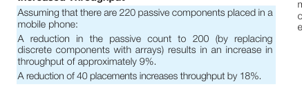
For high volume users of cap arrays using the very latest placement equipment capable of placing 10 components per second, the increase in throughput can be very significant and can have the overall effect of reducing the number of placement machines required to mount components:
If 120 million 2-element arrays or 40 million 4-element arrays were placed in a year, the requirement for placement equipment would be reduced by one machine.
During a 20Hr operational day a machine places 720K components. Over a working year of 167 days the machine can place approximately 120 million. If 2-element arrays are mounted instead of discrete components, then the number of placements is reduced by a factor of two and in the scenario where 120 million 2-element arrays are placed there is a saving of one pick and place machine. Smaller volume users can also benefit from replacing discrete components with arrays. The total number of placements is reduced thus creating spare capacity on placement machines. This in turn generates the opportunity to increase overall production output without further investment in new
equipment.
W2A (0508) Capacitor Arrays
4 pcs 0402 Capacitors = 1 pc 0508 Array
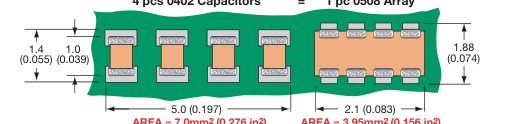
AREA = 7.0mm2 (0.276 in2)
AREA = 3.95mm2 (0.156 in2)
The 0508 4-element capacitor array gives a PCB space saving of over 40% vs four 0402 discretes and over 70% vs four 0603 discrete capacitors.
W3A (0612) Capacitor Arrays
4 pcs 0603 Capacitors = 1 pc 0612 Array
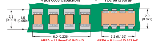
AREA = 13.8mm2 (0.543 in2)
AREA = 6.4mm2 (0.252 in2)
The 0612 4-element capacitor array gives a PCB space saving of over 50% vs four 0603 discretes and over 70% vs four 0805 discrete capacitors.
Page 2
Automotive Capacitor Array (IPC)
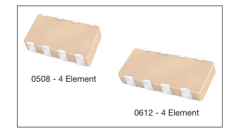
As the market leader in the development and manufacture of capacitor
arrays AVX is pleased to offer a range of AEC-Q200 qualified arrays to
compliment our product offering to the Automotive industry. Both the
AVX 0612 and 0508 4-element capacitor array styles are qualified to the
AEC-Q200 automotive specifications. AEC-Q200 is the Automotive Industry qualification standard and a
detailed qualification package is available on request. All AVX automotive capacitor array production facilities are certified to
ISO/TS 16949:2002.
HOW TO ORDER
Y C 104
3 A 4
W
Voltage Dielectric Capacitance
Case Array Style
Number Z = 10V A = NP0 Code (In pF)
Size W = RoHS
of Caps Y = 16V C = X7R
Significant
2 = 0508 L = SnPb
3 = 25V F = X8R
Digits +
3 = 0612
5 = 50V
Number of
1 = 100V
Zeros e.g. 10μF=106
\*Contact factory for availability by part number for K = ±10% and J = ±5% tolerance.
K
4
T
2A
Capacitance Failure Rate
Packaging
Terminations
Tolerance
& Quantity
4 = Automotive
\*T = Plated Ni and Sn
Code
\*J = ±5%
\*Z = FLEXITERM®
2A = 7" Reel
\*K = ±10%
B = 5% min lead
(4000)
M = ±20%
X = FLEXITERM®
4A = 13" Reel
with 5% min lead
(10000) 2F = 7" Reel
\*RoHS compliant
(1000)
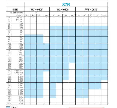
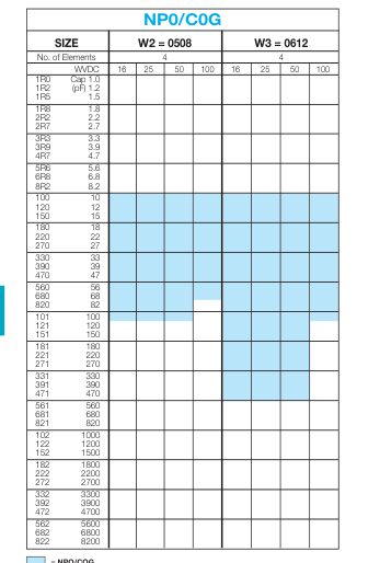
= X7R
Not RoHS Compliant
= NPO/COG
LEAD-FREE COMPATIBLE
COMPONENT
For RoHS compliant products, please select correct termination style.
Page 3
Capacitor Array
PART & PAD LAYOUT DIMENSIONS
millimeters (inches)
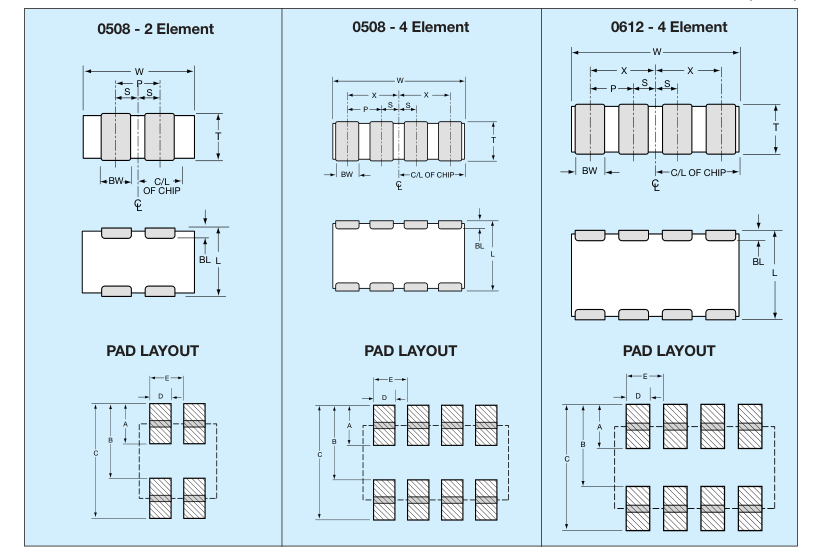
PART DIMENSIONS
0508 - 2 Element
| L | W | T | BW | BL | P | S |
| 1.30 ± 0.15 (0.051 ± 0.006) | 2.10 ± 0.15 (0.083 ± 0.006) | 0.94 MAX (0.037 MAX) | 0.43 ± 0.10 (0.017 ± 0.004) | 0.33 ± 0.08 (0.013 ± 0.003) | 1.00 REF (0.039 REF) | 0.50 ± 0.10 (0.020 ± 0.004) |
0508 - 4 Element
PAD LAYOUT DIMENSIONS
0508 - 2 Element
| A | B | C | D | E |
| 0.68 (0.027) | 1.32 (0.052) | 2.00 (0.079) | 0.46 (0.018) | 1.00 (0.039) |
0508 - 4 Element
| L | W | T | BW | BL | P | X | S |
| 1.30 ± 0.15 (0.051 ± 0.006) | 2.10 ± 0.15 (0.083 ± 0.006) | 0.94 MAX (0.037 MAX) | 0.25 ± 0.06 (0.010 ± 0.003) | 0.20 ± 0.08 (0.008 ± 0.003) | 0.50 REF (0.020 REF) | 0.75 ± 0.10 (0.030 ± 0.004) | 0.25 ± 0.10 (0.010 ± 0.004) |
| A | B | C | D | E |
| 0.56 (0.022) | 1.32 (0.052) | 1.88 (0.074) | 0.30 (0.012) | 0.50 (0.020) |
0612 - 4 Element
0612 - 4 Element
| L | W | T | BW | BL | P | X | S |
| 1.60 ± 0.20 (0.063 ± 0.008) | 3.20 ± 0.20 (0.126 ± 0.008) | 1.35 MAX (0.053 MAX) | 0.41 ± 0.10 (0.016 ± 0.004) | +0.25 0.18 -0.08 (0.007+ 0 . 0 1 0 ) -0.003 | 0.76 REF (0.030 REF) | 1.14 ± 0.10 (0.045 ± 0.004) | 0.38 ± 0.10 (0.015 ± 0.004) |
| A | B | C | D | E |
| 0.89 (0.035) | 1.65 (0.065) | 2.54 (0.100) | 0.46 (0.018) | 0.76 (0.030) |