


 Download PDF
Switch-mode solenoid driver
Document overview
- PDF pages: 8
Technical content
Page 1
®
SWITCH-MODE SOLENOID DRIVER
HIGH VOLTAGE OPERATION (UP TO 50V) HIGH OUTPUT CURRENT CAPABILITY (UP TO 4A) LOW SATURATION VOLTAGE TTL-COMPATIBLE INPUT OUTPUT SHORT CIRCUIT PROTECTION (TO GROUND, TO SUPPLY AND ACROSS THE LOAD) THERMAL SHUTDOWN OVERDRIVING PROTECTION LATCHED DIAGNOSTIC OUTPUT
DESCRIPTION
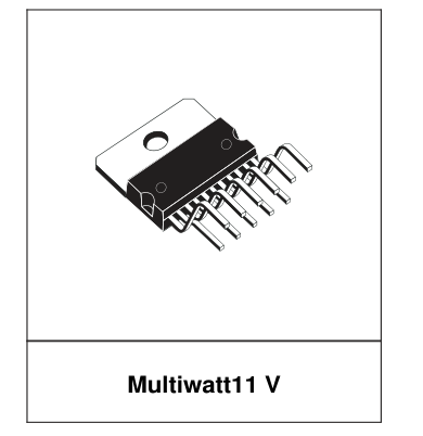
The L294 is a monolithic switched mode solenoid driver designed for fast, high current applications such as hummer and needle driving in printers and electronic typewriters. Power dissipation is reduced by efficient switchmode operation. An extra
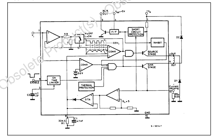
BLOCK DIAGRAM
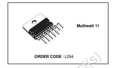
feature of the L294 is a latched diagnostic output which indicates when the output is short circuited. The L294 is supplied in a 11-lead Multiwatt® plastic power package.
September 2003
1/8
Page 2
ABSOLUTE MAXIMUM RATING
| Symbol | Parameter | Value | Unit |
|---|---|---|---|
| Vs | Power Supply Voltage | 50 | V |
| V SS | Logic Supply Voltage | 7 | V |
| V EN | Enable Voltage | 7 | V |
| Ip | Peak Output Current (repetitive) | 4.5 | A |
| P tot | Total Power Dissipation (at Tcase = 75 °C) | 25 | W |
| T , T stg j | Storage and Junction Temperature | - 40 to 150 | °C |
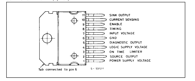
CONNECTION DIAGRAM (top view)
THERMAL DATA
| Symbol | d o Parameter | Value | Unit |
|---|---|---|---|
| Rth-j-case | r P Thermal resistance junction-case Max | 3 | °C/W |
2/8
Page 3
ELECTRICAL CHARACTERISTICS (refer to the test circuit, Vs = 40 V, Vss = 5V, Tamb = 25 °C, unless
otherwise specified)
| Symbol | Parameter | Test conditions | Min. | Typ. | Max. | Unit |
|---|---|---|---|---|---|---|
| V s | Power Supply Voltage (pin 1) | Operative Condition | 12 | 46 | V | |
| I d | Quiescent Drain Current (pin 1) | V = H ENABLE | 20 | 30 | mA | |
| Vi ≥ 0.6V; V ENABLE = L | 70 | |||||
| V ss | Logic Suply Voltage (pin 4) | 4.5 | 7 | V | ||
| Iss | Quiescent Logic Supply Current | V = L DIAG | 5 | 8 | mA | |
| DIAG Output at High Impedance | 10 | 100 | µA | |||
| V i | Input Voltage (pin 7) | Operating Output | 0.6 | V | ||
| Non-operative Output | 0.45 | |||||
| Ii | Input Current (pin 7) | V i ≥ 0.6V | -1 | µA | ||
| V i ≤ 0.45V | -3 | |||||
| V ENABLE | Enable Input Voltage (pin 9) | Low Level | -0.3 | 0.8 | V ) | |
| High Level | 2.4 | |||||
| I ENABLE | Enable Input Current (pin 9) | V = L ENABLE | s ( t -100 | µA | ||
| V = H ENABLE | u | c 100 | ||||
| I / V load i | Trasconductance | RS = 0.2 Ω V i = 1V Vi = 4V | 0.95 | d 1 | 1.05 | A/V |
| o r 0.97 | 1 | 1.3 | ||||
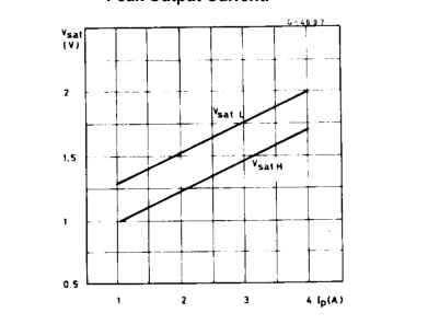
| V sat H | Source Output Saturation Voltage | e Ip = 4A | P | 1.7 | V | |
| V sat L | Sink Output Saturation Voltage | t e l Ip = 4A | 2 | V | ||
| V V sat H + satL | Total Saturation Voltage | o I = 4A p | 4.5 | V | ||
| Ileakage | Output Leakage Current | s b Rs = 0.2Ω; Vi ≤ 0.45 V | 1 | mA | ||
| K | On Time Limiter Constant (°) | O V = L ENABLE | 120 | |||
| V DIAG | Diagnostic Output Voltage (pin 5) | - ) I = 10 mA DIAG s | 0.4 | V | ||
| I DIAG | ( t c Diagnostic Leakage Current (pin 5) | V = 40V DIAG | 10 | µA | ||
| V 8 pin Vpin 10 | u d OP AMP and OTA CD Voltage o Gain (°°) | V = 100 to 800 mV pin10 | 5 | |||
| V SENS | r P Sensing Voltage (pin 10) (°°°) | 0.9 | V |
(°) After a time interval tmax = KC2, the output stages are disabled. (°°) See the block diagram. (°°°) Allowed range of VSENS without intervention of the short circuit protection.
3/8
Page 4
CIRCUIT OPERATION
The L294 work as a trasconductance amplifier: it can supply an output current directly proportional to an input voltage level (Vi). Fyrthermore, it allows complete switching control of the output current waveform (see fig. 1). The following explanation refers to the Block Diagram, to fig. 1 and to the typical application circuit of fig. 2. The ton time is fixed by the width of the Enable input signal (TTL compatible): it is active low and enables the output stages "source" and "sink". At the end of ton, the load current Iload recirculates through D1 and D2, allowing fast current turn-off. The rise time tr, depends on the load characteristics, on Vi and on the supply voltage value (Vs,
pin 1). During the ton time, Iload is converter into a voltage signal by means of the external sensing resistance Rs connected to pin 10. This signal, amplified by the op amp and converted by the transconductance amplifier OTA, charges the external RC network at pin 8 (R1, C1). The voltage at this pin is sensed by the inverting input of a comparator. The voltage on the non-inverting input of this one is fixed by the external voltage Vi (pin 7). After tr, the comparator switches and the output stage "source" is switched off. The comaprator output is confirmed by the voltage on the non-inverting input, which decreases of a costant fraction of Vi (1/10), allowing hysteresis operation. The current in
the load now flow through D1. Two Cases are possible: the time constant of the recirculation phase is higher than R1.C1; the time constant is lower than R1.C1. In the first case, the voltage sensed in the non-inverting input of the comparator is just the value proportional to Iload. In the second case, when the current decreases too quickly, the comparator senses the voltage signal stored in the R1 C1 network. In the first case t1 depends on the load characteristics, while in the second case it depends only on the value of R1. C1. In the other words, R1. C1 fixes the minimum value of t1 )t1 ≥ 1/10 R1.C1. Note that C1 should be chosen in the range 2.7 to 10 nF for stability reasons
of the OTA). After t1, the comparator switches again: the output is confirmed by the voltage on the non-inverting input, which reaches Vi again (hysteresis). Now the cycle starts again: t2, t4 and t6 have the same characteristics as tr, while t3 and t5 are similar
4/8
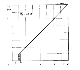
to t1. The peak current Ip depends on Vi as shown in the typical transfer function of fig.3. It can be seen that for Vi lower than 450 mV the device is not operating. For Vi greater than 600 mV, the L294 has a transconductance of 1A/V with Rs = 0.2Ω. For Vi in- cluded between 450 and 600 mV, the operation is not guaranteed. The order parts of the device have protection and diagnostic functions. At pin 3 is connected an ex- ternal capacitor C2, charged at costant current when the Enable is low. After a time interval equal to K C2 (K is defined in the table of Electrical Characteristics and has the dimensions of ohms) the output stages are switched off independently by the Input signal.
This avoids the load being driven in conduction for an excessive period of time (overdriving protection). The action of this protection is shown in fig. 1b. Note that the voltage ramp at pin 3 starts whenever the Enable signal becomes active (low state), regardless of the Input signal. To reset pin 3 and to restore the normal conditions, pin 9 must return high. This protection can be disabled by grounding pin 3. The thermal protection included in the L294 has a hysteresis. It switches off the output stages whenever the junction temperature increases too much. After a fall of about 20°C, the circuit starts again. Finally, the device is protected against any type of
short circuit at the outputs: to ground, to supply and across the load. When the source stage current is higher than 5A and/or when the pin 10 voltage is higher then 1V (i.e. for a sink current greater than 1V/Rs) the output stages are switched off and the device is inhibited. This condition is indicated at the open-collector output DIAG (pin 5); the internal flip-flop F/F changes and forces the output transistor into saturation. The F/F must be supplied independently through Vss (pin 4). The DIAG signal is reset and the output stages are still operative by switching the device on again. After that, two cases are possible: the reason for the "bad operation" is still present
and the protection acts again; the reason has been removed and the device starts to work properly.
Page 5
Figure 1. Output Current Waveforms.
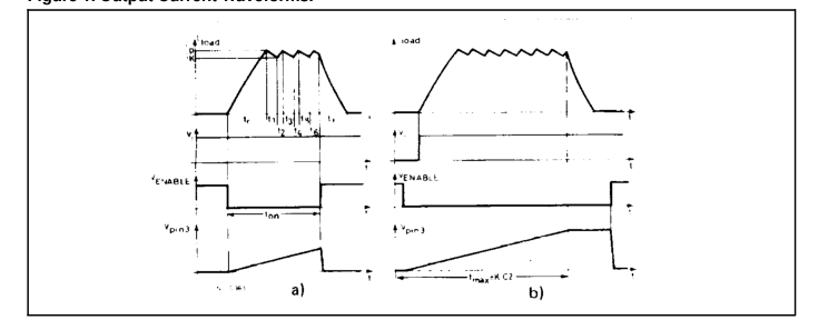
Figure 2. Test and Typical Application Circuit.
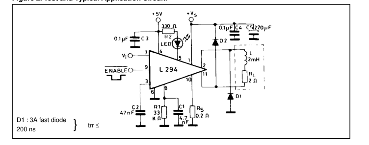
Figure 3. Peak Output Current vs. Input
Figure 4. Output Saturation Voltage vs.
Voltage.
Peak Output Current.
5/8
Page 6
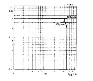
Figure 5. Safe Operating Areas.
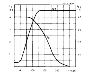
Figure 6. Turn-off Phase.
CALCULATION OF THE SWITCHING TIMES
Referring to the block diagram and to the waveforms of fig. 1, it is possible to calculate the switching times by means of the following relationships. RL In (1 − RL tr = − L
V1 • Ip )
tf = − L In
V2
RL V2 + RL • Io
where : V1 = Vs - Vsat L - Vsat H _ VR sens
where : V2 = Vs + VD1 + VD2
IK ≤ Io ≤ Ip Io is the value of the load current at the end of ton.
a) − L In 0.9 Ip • RL + V3
t1 = t3 = t5 = ...
where
V3 = Vsat L + VR sens + VD1
Ip RL + V3 RL
= b) − R1 C1 In 0.9 ≅ 1
R1 C1 10
RL In ( V1 − Ip RL
t2 = t4 = t6 = ...
= − L
)
V1 − IK RL
Note that the time interval t1 = t3 = t5 = ... takes the longer value between case a) and case b). The switching frequency is always :
1
fswitching =
t1 + t2
In the case a) the main regulation loop is always closed and it forces :
IK = (0.9 ± S) Ip where : S = 3 % @ Vi = 1 V S = 1.5 % @ Vi = 4 V In the case b), the same loop is open in the recirculation phase and IK, which is always lower than 0.9 Ip, is obtained by means of the following relationship.
RL (1 − e − t1 RL
IK = Ip e − t1 RL
− V3
)
L
L
With the typical application circuit, in the conditions Vs = 40V, Ip = 4A, the following switching times result: tr = 255 µs tf = 174 µs @ Io = Ip
t1 = a) 70 µs b) 16 µs t2 = 29 µs f = 10.2 KHz
6/8
Page 7
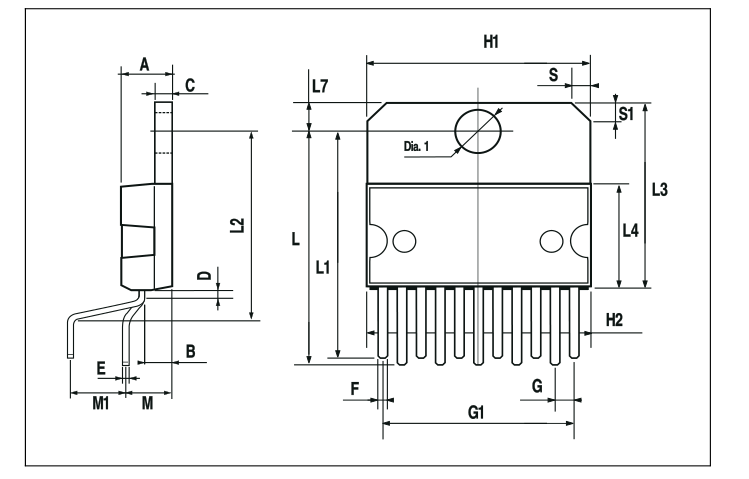
| DIM. | mm | inch | ||||
| MIN. | TYP. | MAX. | MIN. | TYP. | MAX. | |
| A | 5 | 0.197 | ||||
| B | 2.65 | 0.104 | ||||
| C | 1.6 | 0.063 | ||||
| D | 1 | 0.039 | ||||
| E | 0.49 | 0.55 | 0.019 | 0.022 | ||
| F | 0.88 | 0.95 | 0.035 | 0.037 | ||
| G | 1.45 | 1.7 | 1.95 | 0.057 | 0.067 | 0.077 |
| G1 | 16.75 | 17 | 17.25 | 0.659 | 0.669 | 0.679 |
| H1 | 19.6 | 0.772 | ||||
| H2 | 20.2 | 0.795 | ||||
| L | 21.9 | 22.2 | 22.5 | 0.862 | 0.874 | 0.886 |
| L1 | 21.7 | 22.1 | 22.5 | 0.854 | 0.87 | 0.886 |
| L2 | 17.4 | 18.1 | 0.685 | 0.713 | ||
| L3 | 17.25 | 17.5 | 17.75 | 0.679 | 0.689 | 0.699 |
| L4 | 10.3 | 10.7 | 10.9 | 0.406 | 0.421 | 0.429 |
| L7 | 2.65 | 2.9 | 0.104 | 0.114 | ||
| M | 4.25 | 4.55 | 4.85 | 0.167 | 0.179 | 0.191 |
| M1 | 4.73 | 5.08 | 5.43 | 0.186 | 0.200 | 0.214 |
| S | 1.9 | 2.6 | 0.075 | 0.102 | ||
| S1 | 1.9 | 2.6 | 0.075 | 0.102 | ||
| Dia1 | 3.65 | 3.85 | 0.144 | 0.152 | ||
7/8
Page 8
Information furnished is believed to be accurate and reliable. However, STMicroelectronics assumes no responsibility for the consequences of use of such information nor for any infringement of patents or other rights of third parties which may result from its use. No license is granted by implication or otherwise under any patent or patent rights of STMicroelectronics. Specifications mentioned in this publication are subject to change without notice. This publication supersedes and replaces all information previously supplied. STMicroelectronics products are not authorized for use as critical components in life support devices or systems without express written approval of STMicroelectronics.
The ST logo is a registered trademark of STMicroelectronics. All other names are the property of their respective owners
© 2003 STMicroelectronics - All rights reserved
STMicroelectronics GROUP OF COMPANIES
Australia – Belgium - Brazil - Canada - China – Czech Republic - Finland - France - Germany - Hong Kong - India - Israel - Italy - Japan - Ma-
laysia - Malta - Morocco - Singapore - Spain - Sweden - Switzerland - United Kingdom - United States
www.st.com
8/8