


 Download PDF
DATASHEET SEARCH SITE
Document overview
- PDF pages: 8
Technical content
Page 1
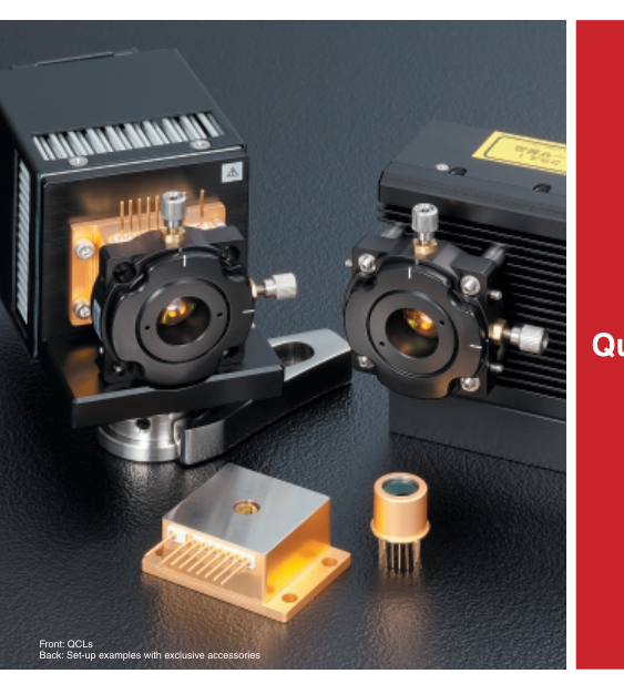
Quantum Cascade Laser
Quantum Cascade Lasers are semiconductor lasers that offer peak emission in the mid-IR range (4 µm to 10 µm). They have
gained considerable attention as a new light source for mid-IR applications such as molecular gas analysis.
Features
GMid-IR laser (4 µm to 10 µm) GCompact, lightweight GTrace gas analysis Environmental measurement, Combustion gas measurement, Plasma measurement, In vivo gas analysis
Applications
GIR molecular spectroscopy Chemical sensing, Molecular oscillation
Page 2
QCL LINEUP
IDFB-CW Type
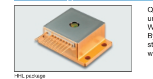
Quantum Cascade Lasers, using structures of SPC (Single Phonon-Continu- um) depopulation and DFB (Distributed Feedback), emit CW (Continuous Wave) mid-IR laser under room temperature.
By controlling the chip's operating temperature through the Peltier element in- stalled in the HHL package, it is possible to tune the emission wavelength
without mode hopping while keeping longitudinal single mode operation.
| Type No. | Wavelength | Operating temperature (QCL) (*1) | Line width (*2) | Tunable range (*3) | Output power | Threshold current | Side-mode suppression ratio (SMSR) | |
|---|---|---|---|---|---|---|---|---|
| Typ. | Min. | Max. | Max. | Min. | Min. | Max. | Min. | |
| L12004-2209H-C | 4.53 µm | +10 °C | +50 °C | 0.2 cm-1 (*4) | ±1.0 cm-1 | 20 mW | 1.0 A | 25 dB |
| Condition: K=2209 cm-1 (*5) | Condition: Top(qcl)=20 °C | |||||||
| L12004-2190H-C | 4.57 µm | +10 °C | +50 °C | 0.2 cm-1 (*4) | ±1.0 cm-1 | 20 mW | 1.0 A | 25 dB |
| Condition: K=2190 cm-1 (*5) | Condition: Top(qcl)=20 °C | |||||||
| L12005-1900H-C | 5.26 µm | +10 °C | +50 °C | 0.2 cm-1 (*4) | ±1.0 cm-1 | 20 mW | 1.0 A | 25 dB |
| Condition: K=1900 cm-1 (*5) | Condition: Top(qcl)=20 °C | |||||||
| L12006-1631H-C | 6.13 µm | +10 °C | +50 °C | 0.2 cm-1 (*4) | ±1.0 cm-1 | 20 mW | 1.0 A | 25 dB |
| Condition: K=1631 cm-1 (*5) | Condition: Top(qcl)=20 °C | |||||||
| L12007-1294H-C | 7.73 µm | +10 °C | +50 °C | 0.2 cm-1 (*4) | ±1.0 cm-1 | 20 mW | 1.0 A | 25 dB |
| Condition: K=1294 cm-1 (*5) | Condition: Top(qcl)=20 °C | |||||||
(\*1) This specifies the temperature range within which the target emission wavenumber (K) can be realized. (\*2) Full-width half maximum (\*3) This specifies the continuous tunable range (without mode hopping). The center wavenumber of the tuning range is the emission wavenumber (K). (\*4) The figures are limited by the resolution and signal/noise ratio of the measuring instruments used. (\*5) K: Emission wavenumber (cm-1)
I Limited quantities of QCLs with emission wavelengths close to those specified above may be available occasionally.
Please contact a Hamamatsu sales office for information on available stock.
Characteristics examples
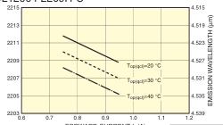
GL12004-2209H-C
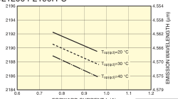
GL12004-2190H-C
| Parameter | Symbol | Condition | Typical value |
|---|---|---|---|
| Temperature coefficient of wavenumber | δKT | If fixed | -0.18 cm-1/°C |
| Current coefficient of wavenumber | δKC | Top(qcl) fixed | -0.015 cm-1/mA |
FORWARD CURRENT If (A)
GL12005-1900H-C
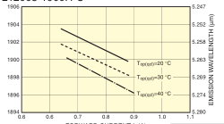
FORWARD CURRENT If (A)
| Parameter | Symbol | Condition | Typical value |
|---|---|---|---|
| Temperature coefficient of wavenumber | δKT | If fixed | -0.18 cm-1/°C |
| Current coefficient of wavenumber | δKC | Top(qcl) fixed | -0.015 cm-1/mA |
GL12006-1631H-C
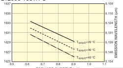
| Parameter | Symbol | Condition | Typical value |
|---|---|---|---|
| Temperature coefficient of wavenumber | δKT | If fixed | -0.14 cm-1/°C |
| Current coefficient of wavenumber | δKC | Top(qcl) fixed | -0.016 cm-1/mA |
FORWARD CURRENT If (A)
GL12007-1294H-C
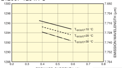
FORWARD CURRENT If (A)
| Parameter | Symbol | Condition | Typical value |
|---|---|---|---|
| Temperature coefficient of wavenumber | δKT | If fixed | -0.15 cm-1/°C |
| Current coefficient of wavenumber | δKC | Top(qcl) fixed | -0.015 cm-1/mA |
CLASS 3B LASER
Invisible Laser Radiation: Avoid Exposure to Beam
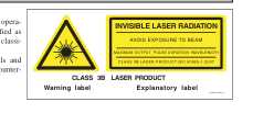
GThe Laser emits invisible laser radiation. The instrument which used the LASER, operated under ordinary conditions, is classified as Class 3B according to the laser product classification code IEC 60825-1.
| Parameter | Symbol | Condition | Typical value |
|---|---|---|---|
| Temperature coefficient of wavenumber | δKT | If fixed | -0.1 cm-1/°C |
| Current coefficient of wavenumber | δKC | Top(qcl) fixed | -0.01 cm-1/mA |
FORWARD CURRENT If (A)
See IEC 60825-1, -14 for more details and safety operation concerning the above countermeasures.
Page 3
IDFB-Pulsed Type
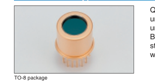
Quantum Cascade Lasers, using structures of SPC (Single Phonon-Continu- um) depopulation and DFB (Distributed Feedback), emit pulsed mid-IR laser under room temperature.
By controlling the chip's operating temperature through the Peltier element in- stalled in the TO-8 package, it is possible to tune the emission wavelength
without mode hopping while keeping longitudinal single mode operation.
| Type No. | Wavelength | Operating temperature (QCL) (*1) | Line width (*2) | Tunable range (*3) | Pulsed output power | Threshold current | Side-mode suppression ratio (SMSR) | |
|---|---|---|---|---|---|---|---|---|
| Typ. | Min. | Max. | Max. | Min. | Min. | Max. | Min. | |
| L12014-2231T-C | 4.48 µm | -10 °C | +50 °C | 0.2 cm-1 (*4) | ±1.0 cm-1 | 50 mW | 1.5 A | 25 dB |
| Condition: K=2231 cm-1 (*5) | ||||||||
| L12015-1901T-C | 5.26 µm | -10 °C | +50 °C | 0.2 cm-1 (*4) | ±1.0 cm-1 | 50 mW | 1.5 A | 25 dB |
| Condition: K=1901 cm-1 (*5) | ||||||||
| L12016-1630T-C | 6.13 µm | -10 °C | +50 °C | 0.2 cm-1 (*4) | ±1.0 cm-1 | 50 mW | 1.5 A | 25 dB |
| Condition: K=1630 cm-1 (*5) | ||||||||
| L12017-1278T-C | 7.82 µm | -10 °C | +50 °C | 0.2 cm-1 (*4) | ±1.0 cm-1 | 50 mW | 1.5 A | 25 dB |
| Condition: K=1278 cm-1 (*5) | ||||||||
Standard driving conditions: tw=10 ns, fr=200 kHz, Top(qcl)=20 °C (\*1) This specifies the temperature range within which the target emission wavenumber (K) can be realized. (\*2) Full-width half maximum (\*3) This specifies the continuous tunable range (without mode hopping). The center wavenumber of the tuning range is the emission wavenumber (K). (\*4) The figures are limited by the resolution and signal/noise ratio of the measuring instruments used. (\*5) K: Emission wavenumber (cm-1)
Characteristics examples
GL12014-2231T-C
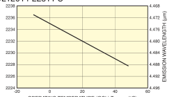
OPERATING TEMPERATURE (QCL) Top(qcl) (°C)
Typical value
Parameter Symbol Condition Temperature coefficient δKT -0.15 cm-1/°C Ifp fixed
of wavenumber
GL12016-1630T-C
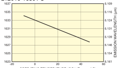
OPERATING TEMPERATURE (QCL) Top(qcl) (°C)
Parameter Symbol Condition Typical value
Temperature coefficient
Ifp δKT -0.11 cm-1/°C
of wavenumber
fixed
GL12015-1901T-C
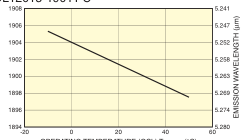
OPERATING TEMPERATURE (QCL) Top(qcl) (°C)
Typical value
Parameter Symbol Condition Temperature coefficient δKT -0.13 cm-1/°C Ifp fixed
of wavenumber
GL12017-1278T-C
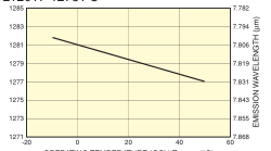
OPERATING TEMPERATURE (QCL) Top(qcl) (°C)
Parameter Symbol Condition Typical value
Temperature coefficient δKT -0.08 cm-1/°C Ifp fixed
of wavenumber
CLASS 3R LASER
Invisible Laser Radiation: Avoid Direct Exposure of eyes to Beam
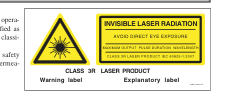
GThe Laser emits invisible laser radiation. The instrument which used the LASER, operated under ordinary conditions, is classified as Class 3R according to the laser product classification code IEC 60825-1. See IEC 60825-1 for more details and safety operation concerning the above countermeasures.
Page 4
QCL LINEUP
IDFB-CW Type
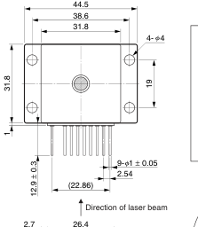
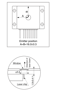
Dimensional outline (unit: mm)
HHL package
| 2.9 3.4 | q ert | yuio!0 | 14.8 |
(\*1) Tolerance is +/- 0.2 mm unless specified. (\*2) Edge of QCL chip and outside of the package
| PIN No. (*3 | ) FUNCTION | PIN No. (*3) | FUNCTION |
| q | TEC Cathode (-) | u | QCL Cathode (-) |
| e | N.C. | i | Thermistor (Top(c)) |
| r | QCL Anode (+) | o | Thermistor (Top(c)) |
| t | Thermistor (Top(qcl)) | !0 | TEC Anode (+) |
| y | Thermistor (Top(qcl)) | — | — |
(\*3) e is electrically connected to the package. The other pins are electrically isolated from the package.
CONNECTION EXAMPLE
IDFB-Pulsed Type
Dimensional outline (unit: mm)
TO-8 package
Direction of laser beam
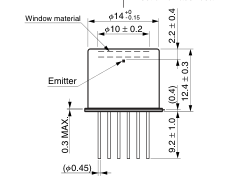
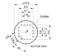
| PIN No. | FUNCTION | PIN No | . FUNCTION | PIN No. | FUNCTION |
| q | TEC Cathode (-) | u | QCL Anode (+) | !3 | QCL Cathode (-) |
| w | N.C. | i | QCL Anode (+) | !4 | QCL Cathode (-) |
| e | N.C. | o | Thermistor (Top(qcl)) | !5 | QCL Cathode (-) |
| r | TEC Anode (+) | !0 | Thermistor (Top(qcl)) | !6 | QCL Cathode (-) |
| t | QCL Anode (+) | !1 | N.C. | — | — |
| y | QCL Anode (+) | !2 | N.C. | — | — |
\* All the pins are electrically isolated from the package.
Page 5
PERIPHERAL INSTRUMENTS AND ACCESSORIES
IHHL Mount A11709 Series
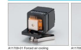
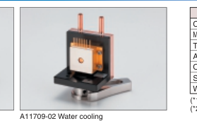
\* Mounts shown in photos have HHL package QCL.
Cooling Unit for HHL packaged QCL. Two types of cooling, forced air and water, are available. An Aspheric ZnSe Lens Unit A11331-0xH can be mounted.
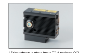
ITO-8 Pulse Driver C11635
| Parameter | A11709-01 | A11709-02 | Unit |
|---|---|---|---|
| Cooling method | Forced air cooling | Water cooling | — |
| Maximum heat discharge power | Approx. 30 (*1) | Approx. 50 (*2) | W |
| Thermal resistance | Approx. 0.5 (*1) | Approx. 0.3 (*2) | °C/W |
| Applicable package | HHL | — | |
| Operating temperature | 0 to +40 | °C | |
| Size (W × H × D) | 68 × 82 × 117 | 60 × 103 × 50 | mm |
| Weight | 0.5 | 0.52 | kg |
(\*1) DC fan speed 7600 min-1 at ambient temperature 25 °C (\*2) Necessary flow rate and water temperature: 2000 cc/min. at 20 °C
Features
GTwo types of cooling (water, forced air)
are available.
GEasy to mount GEasily set on optical tables GCan be mounted to the lens unit A11331-0xH
| Parameter | Symbol | Value | Unit | |
|---|---|---|---|---|
| Output current | Output current range | I(pulse) | 0 to 3 | A |
| Pulse width (Typ.) | Pw | 10 | ns | |
| Rise / fall time (Typ.) | Tr | 5 | ns | |
| Repetition frequency | — | Approx. 150 kHz to Approx. 1 MHz | — | |
| Duty ratio | DR | <5 | % | |
| Dimensions (W × H × D) | — | 90 × 68 × 43 | mm | |
| Weight | — | 0.3 | kg | |
\* can be mounted to aspheric lens unit A11331-0xH. \* repetition frequency up to 2 MHz \* pulse width down to 40 ns (repetition frequency < 500 kHz)
\* Driver shown in photo has a TO-8 package QCL.
\* pulse width up to 1000 ns (repetition frequency < 100 kHz) \* external trigger operation by removing the oscillating board
Pulsed QCL Driver for TO-8 packaged pulsed QCL. It
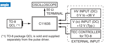
\* Two types of DC power supplies and a TEC driver are separately needed
outputs low noise pulsed current, and TO-8 packaged
\* An oscilloscope is separately needed for observation of current output shape.
pulsed QCL can be mounted directly.
\* Bias source or TTL gate source should be separately prepared at the needs of usage.
An Aspheric ZnSe Lens Unit A11331-0xH can be
mounted.
Setup example
Features
GCan be connected to TO-8 package QCL GPulse width: 10 ns (Typ.)
Repetition frequency: <1 MHz
GLow noise, high stability GDesigned to be built into an instrument
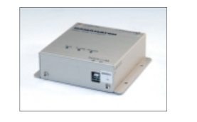
ITEC Driver C11330 Series
| Parameter | C11330-01 | C11330-02 | Unit | |
|---|---|---|---|---|
| Applicable package | HHL | TO-8 | — | |
| TEC output (*1) | TEC control current | -8 to +8 | -1.9 to +1.9 | A |
| Compliance voltage | ±24 | V | ||
| Temperature sensor (*2) | Thermistor | NTC, 2 lines | — | |
| RTD sensor | 3-line platinum temperature measurement resistance (Pt100) | — | ||
| Temperature control | Temperature control range (Thermistor/RTD) | -50 to +125 / -50 to +150 | °C | |
| Setup resolution | 0.01 | °C | ||
| Temperature stability | ±0.01 (Typ.) | °C | ||
| Control frequency | 0.1 to 100 | s | ||
| Control algorithm | Digital PID loop (*3) | — | ||
| Host interface | RS-232C, RS-422 | — | ||
| Main body size (W × H × D) | 100 × 110 × 33 | mm | ||
| Weight | 0.3 | kg | ||
Peltier TEC (thermoelectric cooler) driver is used to control QCL temperature with high accuracy and high stability. Designed to be built into an instrument.
(\*1) Actual output depends on characteristics of the connected load (TEL module), input power supply voltage, and current.
Features
GHigh accuracy, high stability
(\*2) Thermistor and Pt100 cannot be used simultaneously; select one of them.
GTemperature stability: 0.01 °C
(\*3) Auto-tuning function can be set by the host interface.
GTEC heatsink monitoring function
\* This can be controlled from a PC through RS-232C or RS-422.
GBipolar output, digital PID control
\* A power supply (DC 24V), power cable, output cable, communication cable, terminal for control are separately needed. \* When controlling through a PC which does not have any ports or terminal emulators for serial communication, use an USB serial converter of HPK's recommendation (Windows7 or later).
Page 6
PERIPHERAL INSTRUMENTS AND ACCESSORIES
ICables
GHHL Socket Cable A11134-01
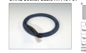
| No. | A | B | C |
| Name | HHL connector | TEC drive cable | QCL drive cable |
| Terminal | 9 pin socket | Cut-off 4PS (8 wires) | Cut-off 2PS (4 wires) |
Terminals B and C are to be modified in ac- cordance with the type of TEC and power supply.
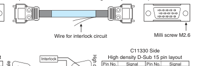
GSignal Cable for C11330 A11134-04
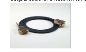
Dimensional outline (unit: mm)
Inch screw #4-40
PC Side D-Sub 9 pin layout Pin No. Signal 1 DCD 2 RxD 3 TxD 4 DTR 5 GND 6 DSR 7 RTS 8 CTS 9 RI
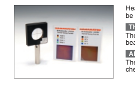
IHeatseeker A10767
Pin layout
Braided outer shield
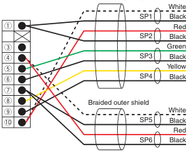
B
!0
C
q !0 q t y i o
r u r u
2 m
D-Sub 9 pin Female
High density D-Sub 15 pin Male
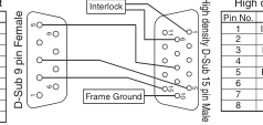
| Pin No. | Signal | Pin No. | Signal |
| 1 | INTERLOCK | 9 | GND |
| 2 | ALARM | 10 | Frame Ground |
| 3 | RS-422 Rx+ | 11 | START |
| 4 | RS-422 Tx+ | 12 | STABLE |
| 5 | RS-232C Rx | 13 | RS-422 Rx- |
| 6 | GND | 14 | RS-422 Tx- |
| 7 | GND | 15 | RS-232C Tx |
| 8 | GND |
Heatseeker A10767 consists of 2 types of thermal viewing card and an alignment target. It can
be used for visualization and alignment of the QCL laser beam.
Thermal Viewing Card
Thermal material provides visibility of the IR laser beam. Facilitates tracing of the invisible laser
beam. Two cards with different sensitivity ranges are provided.
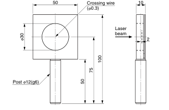
Alignment Target
The light axis of the invisible IR laser beam can be easily aligned. Includes a cross target for
checking the light axis. Thermal viewing card can be inserted.
Dimensional outline (unit: mm)
| Parameter | Description / value | ||
|---|---|---|---|
| Detectable temperature range | Thermal viewing card #01 | 18 to 32 | |
| Thermal viewing card #02 | 30 to 35 | ||
| Usable wavelength range | 1.0 to 20 | ||
| Power required for visibility (*1) | >3 | ||
| Damage threshold (Max. power density) | 20 | ||
| Maximum aperture | 30 | ||
| Storage temperature | -5 to +60 (No condensation) | ||
| Dimensions (W × H × D) | 50 × 100 × 12 | ||
Unit °C
°C µm mW/mm2 mW/mm2 mm °C mm
(\*1) Average power density
Page 7
ILens / Lens Unit
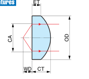
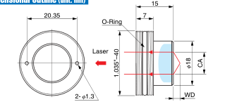
Aspheric ZnSe Lens for QCL. It can be installed into an Aspheric ZnSe Lens Unit A11331-0xH, and can be mounted onto HHL Mount A11709 series and Pulsed QCL Driver C11635.
GAspheric ZnSe Lens A11331-0x
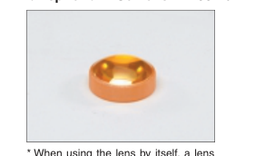
| Parameter | Symbol | A11331-01 | A11331-02 | Unit |
|---|---|---|---|---|
| Primary design wavelength | λ | 8 | 5 | µm |
| Numerical aperture (NA) | NA | 0.78 | — | |
| Effective diameter | CA | 10 | mm | |
| Actual focal distance | EFL | 4.8 | mm | |
| Working distance | WD | 3.0 | mm | |
| Periphery | OD | 14.9 to 15.0 | mm | |
| Center thickness | CT | 6.4 ± 0.2 | 6.3 ± 0.2 | mm |
| Edge thickness | ET | 3 | mm | |
| Material | — | ZnSe | — | |
| Refractive index | n | 2.417 at 8 µm | 2.429 at 5 µm | — |
| AR coating | — | BBAR, T (ave)>97 % (*1) | BBAR, T (ave)>96 % (*2) | — |
| Weight | — | 5 | g | |
holder is required.
(\*1) T (ave): Average transmittance at wavelength 8 µm to 12 µm (\*2) T (ave): Average transmittance at wavelength 4 µm to 8 µm
Features
A11331-01
A11331-02
BBAR / 4 µm to 8 µm
BBAR / 8 µm to 12 µm
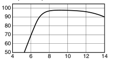
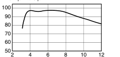
Wavelength (µm)
Wavelength (µm)
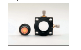
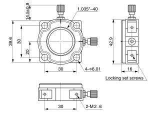
GAspheric ZnSe Lens Unit A11331-0xH
| Parameter | Value | |
|---|---|---|
| Lens mounting unit | Applicable lens | A11331-01 or A11331-02 |
| XYZ translator | X/Y movable range | ±1 mm |
x in the suffix of the part number indicates the type of embedded lens.
Dimensional outline (unit: mm)
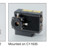
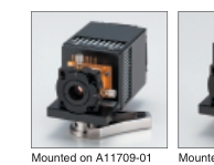
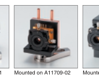
Usage example
A11331-0xH can be mounted on HHL mount A11709 series and pulsed QCL driver C11635.
Page 8
Read carefully before using QCL
Read carefully before using QCL
For safe and effective use of a QCL, carefully read the documents that came with the purchased goods. Also, read carefully to the end of manuals and instructions, and observe the local law regulations about using lasers.
Warning
!
This catalog is not a guarantee of product perfection. When the products are used in an instrument which may cause bodily harm or damage properties, it is dangerous to operate the instrument unless proper safety measures are taken against possible product defects.
Caution
!
GAbsolute maximum ratings Absolute maximum ratings listed in the specification sheet and/or test sheet are limiting values that must not be exceeded even momentarily. Using this product under conditions where any one of the maximum ratings is exceeded may cause serious and irreparable damage to the products. Values in absolute maximum ratings for forward current and forward voltage differ in each product, so always check the values listed in the test sheet that comes with each product and make sure that these values are not exceeded.
GLaser driver power supply Current surges and current fluctuations may impair performance of the laser device. Do not apply reverse current and re- verse voltage to the QCL.
GHeat dissipation This product uses a Peltier element to control temperature of the laser device, so the Joule heat generated in this product must be dissipated. If operated with poor heat dissipation, the device temperature may soon exceed the absolute maximum rating for the operating case temperature listed in specification sheet. Make sure that a proper heatsink is installed on the product. Poor heat dissipation may lead to excessive heating during operation and cause device deterioration or open-circuit faults even if the Peltier current is within the maximum rating. Heat dissipation on the laser side may not be sufficient when supplying electrical current to the Peltier element in heating mode, and cause failures or affect reliability. Carefully
check these points before actual operation.
HAMAMATSU PHOTONICS K.K.
www.hamamatsu.com
HAMAMATSU PHOTONICS K.K., Laser Group, Sales Dept. 1-8-3, Shinmiyakoda, Kita-ku, Hamamatsu City, Shizuoka, 431-2103, Japan, Telephone: (81)53-484-1301, Fax: (81)53-484-1302, E-mail: laser-g@lsr.hpk.co.jp U.S.A.: Hamamatsu Corporation: 360 Foothill Road, P. O. Box 6910, Bridgewater. N.J. 08807-0910, U.S.A., Telephone: (1)908-231-0960, Fax: (1)908-231-1218 E-mail: usa@hamamatsu.com Germany: Hamamatsu Photonics Deutschland GmbH: Arzbergerstr. 10, D-82211 Herrsching am Ammersee, Germany, Telephone: (49)8152-375-0, Fax: (49)8152-2658 E-mail: info@hamamatsu.de France: Hamamatsu Photonics France S.A.R.L.: 19, Rue du Saule Trapu, Parc du Moulin de Massy, 91882 Massy Cedex, France, Telephone: (33)1 69 53 71 00, Fax: (33)1 69 53 71 10 E-mail: infos@hamamatsu.fr
United Kingdom: Hamamatsu Photonics UK Limited: 2 Howard Court, 10 Tewin Road Welwyn Garden City Hertfordshire AL7 1BW, United Kingdom, Telephone: 44-(0)1707-294888, Fax: 44(0)1707-325777 E-mail: info@hamamatsu.co.uk North Europe: Hamamatsu Photonics Norden AB: Torshamnsgatan 35 SE-164 40 Kista, Sweden, Telephone: (46)8-509-031-00, Fax: (46)8-509-031-01 E-mail: info@hamamatsu.se Italy: Hamamatsu Photonics Italia: S.R.L.: Strada della Moia, 1/E, 20020 Arese, (Milano), Italy, Telephone: (39)02-935 81 733, Fax: (39)02-935 81 741 E-mail: info@hamamatsu.it
Cat. No. LQCL2001E04
China: Hamamatsu Photonics (China) Co., Ltd.: 1201 Tower B, Jiaming Center, 27 Dongsanhuan Road North, Chaoyang District, Beijing 100020, China, Telephone: (86)10-6586-6006, Fax: (86)10-6586-2866 E-mail: hpc@hamamatsu.com.cn
SEPT. 2013 IP (1000)