Download PDF
KSG-262 KODENSHI
Document overview
- PDF pages: 2
Technical content
Page 1
Photointerrupter(Transmissive)
KSG-262
DESCRIPTION
DIMENSIONS (UNIT:mm)
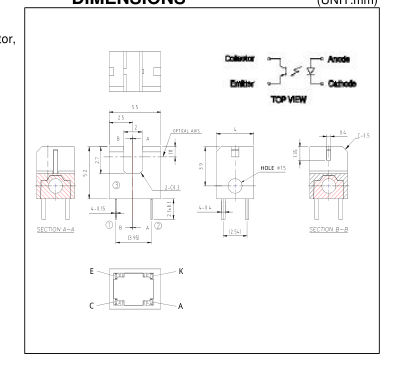
The KSG-262 photointerrupter is high-performance standard type, combines high-output GaAs IRED with high sensitive phototransistor, Compact size.
FEATURES
- Screw - mount type
- GAP : 2.0mm
- Compact
- Widely applicable
APPLICATIONS
- Floppy disk drives
- CD-ROM drives
- Printers
- Facsimiles
- Cameras
ABSOLUTE MAXIMUM RATINGS (Ta=25℃)
| Parameter | Symbol | Rating | |
|---|---|---|---|
| Input | Forward Current | IF | 50 |
| Pulse Forward Current *1 | IFP | 0.5 | |
| Reverse Voltage | VR | 5 | |
| Power Dissipation | PD | 75 | |
| Output | Collector Emitter Voltage | BVCEO | 30 |
| Emitter Collector Voltage | BVECO | 5 | |
| Collector Current | IC | 20 | |
| Collector Power Dissipation | PC | 75 | |
| Operating Temperature *2 | TOPR | -20 ~ +85 | |
| Storage Temperature *2 | TSTG | -30 ~ +100 | |
| Soldering Temperature *3 | TSOL | 260 | |
Unit mA A V mW V V mA mW ℃ ℃ ℃
\*1. tw≤100μsec.period : T=10msec \*2. No icebound or dew \*3. For MAX. 5 seconds at the position of 2mm from the package
ELECTRO-OPTICAL CHARACTERISTICS (Ta=25℃)
| Parameter | Symbol | Conditions | MIN. TYP. | MAX. | Unit | ||
|---|---|---|---|---|---|---|---|
| Input | Forward Voltage | VF | IF=20mA | - 1.25 | 1.5 | V | |
| Reverse Current | IR | VR=5V | - - | 10 | μA | ||
| Capacitance | CD | V=0, f=1KHz | - 25 | - | pF | ||
| Peak Wavelength | λ P | IF=20mA | - 940 | - | nm | ||
| Output | Dark Current | ICEO | VCE=10V, EV=0LX | - 1.0 | 100 | nA | |
| Coupled | Collector Current | IC | VCE=5V, IF=20mA (Non-shading) | 0.25 - | 2.5 | mA | |
| Leakage Current | ICEOD | VCE=5V, IF=10mA (shading) | - 0.5 | 10 | μA | ||
| Collector Emitter Saturation Voltage | VCE(SAT) | IF=10mA, IC=0.3mA | - 0.15 | 0.4 | V | ||
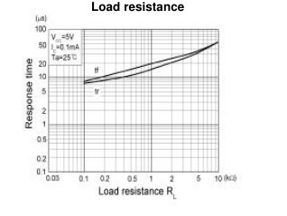
| Response Time | Rise Time | tr | VCC=5V, IC=0.1mA, RL=1kΩ | - 20 | - | µs | |
| Fall Time | tf | - 20 | - | µs | |||
Page 2
Photointerrupter(Transmissive)
KSG-262
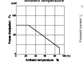
Power dissipation Vs.
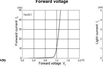
Forward current Vs.
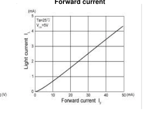
Light current Vs.
Ambient temperature
Forward voltage
Forward current
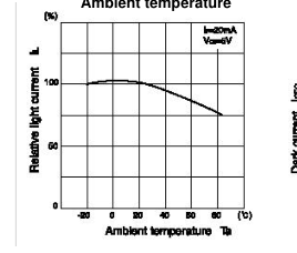
Relative light current Vs.
Light current Vs.
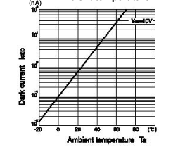
Dark current Vs.
Ambient temperature
Ambient temperature
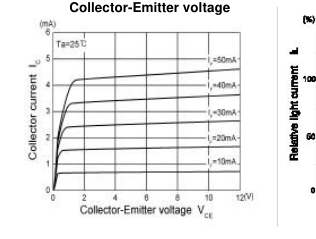
Relative light current Vs.
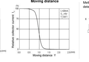
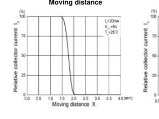
Relative light current Vs. Moving distance
Moving distance
Method of measuring postion detection characteristic 0
Y
0
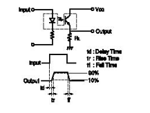
Switching time Vs.
Switching time measurement circuit