


 Download PDF
KP3020W KODENSHI
Document overview
- PDF pages: 4
Technical content
Page 1
- Descriptions
The KP3020W8AA2C is a small and thin form plastic leaded chip carrier(PLCC) 2-pin package
with InGaN Blue Chip White LED..
- Features
◆ Small Footprint Surface Mount Package ( 3.0 L × 2.0 W × 1.3 H [mm3])
◆ Typical Forward Voltage(VF) : 3.3 V @ Forward Current(IF)=20mA
◆ Operation Temperature from -40℃ to +85℃
◆ Soldering methods : IR reflow soldering
◆ Taping : 8mm conductive black carrier tape & antistatic clear cover tape
- Application
◆ Indicatiors, Illuminations
The contents of this data sheet are subject to change without advance notice for the purpose of improvement. When using this product, would you please refer to the latest specifications.
Page 2
- Outline Dimensions and Material Descriptions ◆ Outline Dimensions
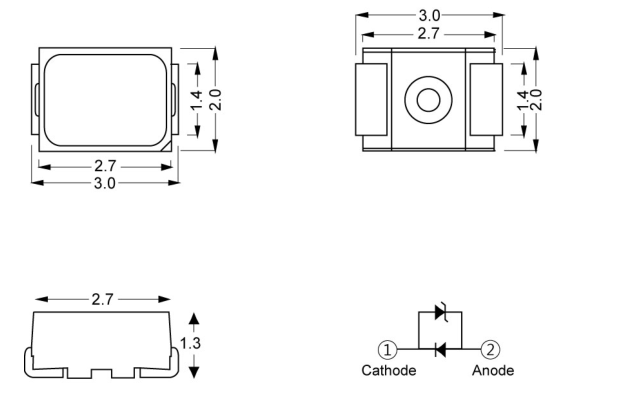
◆ Material Descriptions
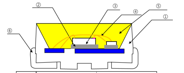
| No. | Item | Material |
| ① | Frame Resine | Polymer |
| ② | Paste | Clear Epoxy |
| ③ | Blue LED Chip | InGaN/AI O 2 3 |
| ④ | Wire | Au |
| ⑤ | Encapsulant | Phosphor Epoxy |
| ⑥ | Electrode | Ag Plated Cu |
The contents of this data sheet are subject to change without advance notice for the purpose of improvement. When using this product, would you please refer to the latest specifications.
Page 3
- Absolute Maximums
| ITEM | Symbol | MIN | MAX | Unit | Conditions |
|---|---|---|---|---|---|
| Forward Current | I F | - | 20 | mA | |
| Peak Forward Current* | I FP | - | 40 | mA | per die |
| Power Dissipation | P D | - | 80 | mW | |
| Reverse Voltage | V R | - | 5 | V | per die |
| Operating Temperature | T OP | -40 | 85 | ℃ | |
| Storage Temperature | Ts | -40 | 100 | ℃ | |
| Soldering Temperature*2 | T sol | - | 260 | ℃ |
\* 1. IFP was measured at Tw ≤ 1 msec of pluse width and D ≤ 1/10 of duty ratio.
\* 2. Soldering time : 5 Sec
- Electro-Optical Characteristics (TA = 25℃)
| ITEM | Symbol | MIN | TYP | MAX | Unit | Conditions |
|---|---|---|---|---|---|---|
| Forward Voltage *3 | V F | 3.0 | - | 3.4 | V | I =20mA F |
| Reverse Current | V R | - | - | 5 | V | I =10uA R |
| Luminous intensity*1,3 | I V | 1500 | - | 3000 | mcd | I =20mA F |
| Half angle *2 | 2θ 1/2 | 120 | - | deg | I =20mA F |
\*1. The Luminous intensity IV was measured at the peak of the spatial pattern which may not aligned with the mechanical axis of the LED package.
\*2. 2 Θ 1/2 is the off-axis where the luminous intensity is 1/2 of the peak intensity.
\*3. Measuring Tolerance - VF : ± 0.1 V, IV : ± 10%, Ra : ± 3, X,Y : ± 0.01
The contents of this data sheet are subject to change without advance notice for the purpose of improvement. When using this product, would you please refer to the latest specifications.
Page 4
- Characteristic Graphs
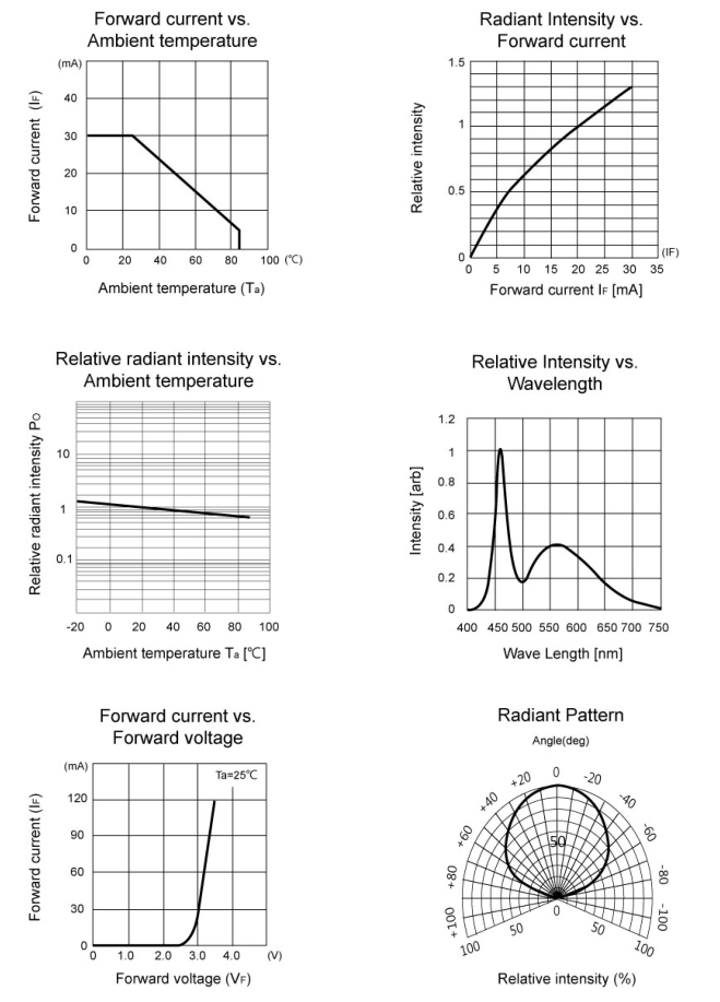
The contents of this data sheet are subject to change without advance notice for the purpose of improvement. When using this product, would you please refer to the latest specifications.