Download PDF
KBT011 KINGBRIGHT
Document overview
- PDF pages: 4
Technical content
Page 1
PRELIMINARY SPEC
Features
1.Opaque,mini-flat package. 2.Subminiature type. 3.Isolation voltage:2000 Vrms. 4.High reliability. 5.Rohs compliant.
Package Dimensions
PHOTOCOUPLER
KBT011
Applications
1.motor-control circuits. 2.computer terminals. 3.system appliances, measuring instruments. 4.programmable logic controller. 5.signal transmission between circuit of different potentials and impedances.
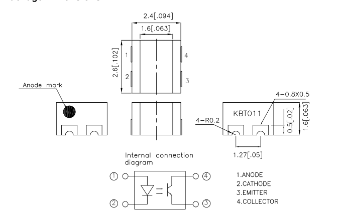
UNIT : MM[INCH] TOLERANCE :±0.2[0.008] UNLESS OTHERWISE NOTED.
REV NO: V.1 DATE: DEC/29/2004 PAGE: 1 OF 4
Page 2
PHOTOCOUPLER
KBT011
\*Absolute Maximum Ratings(Ta=25°C)
| Parameter | Symbol | Rating | Unit | |
|---|---|---|---|---|
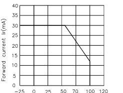
| Input | Forward Current | I F | 30 | mA |
| Reverse Voltage | V R | 6 | V | |
| Power dissipation | P | 35 | mW | |
| Output | Collector-Emitter Voltage | V CEO | 35 | V |
| Emitter-Collector Voltage | V ECO | 6 | V | |
| Collector Current | I C | 30 | mA | |
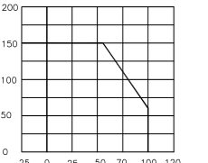
| Collector Power Dissipation | P C | 150 | mW | |
| Total Power Dissipation | Ptot | 170 | mW | |
| *1 Isolation Voltage | Viso | 2000 | Vrms | |
| Operating Temperature | Topr | -30 to +85 | ºC | |
| Storage Temperature | Tstg | -40 to +100 | ºC | |
| *2 Soldering Temperature | Tsol | 260 | ºC | |
\*1 40 to 60%RH,AC for 1 minute. \*2 For 10 seconds.
\*Electro-optical Characteristics(Ta=25°C)
| Parameter | Symbol | Conditions | Min. | TYP. | Max. | Unit | ||
|---|---|---|---|---|---|---|---|---|
| Input | Forward Voltage | V F | I =20mA F | - | 1.2 | 1.4 | V | |
| Peak Forward Voltage | V FM | I =0.5A FM | - | - | 3.0 | V | ||
| Reverse Current | I R | V =4V R | - | - | 10 | µA | ||
| Output | Collector dark current | I CEO | V =20V, I =0mA CE F | - | - | 10-7 | A | |
| Transfer charact- eristics | *1Current transfer ratio | CTR | I =5mA, V =5V F CE | 50 | - | 300 | % | |
| Collector-emitter saturation voltage | V CE (sat) | I =20mA,I =1mA F C | - | - | 0.2 | V | ||
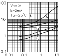
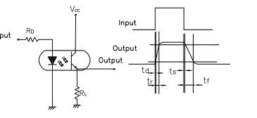
| Response time | Rise time | tr | V =2V CE I =2mA C R=100Ω L | - | 4 | 18 | µs | |
| Fall time | tf | - | 3 | 18 | µs | |||
\*1 Classification table of current transfer ratio is shown below. CTR= Ic X 100% FI
REV NO: V.1 DATE: DEC/29/2004 PAGE: 2 OF 4
Page 3
PHOTOCOUPLER
KBT011
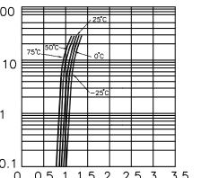
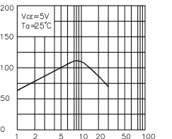
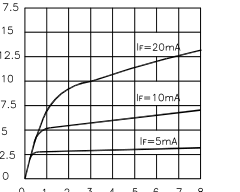
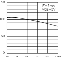
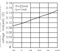
REV NO: V.1 DATE: DEC/29/2004 PAGE: 3 OF 4
Page 4
PHOTOCOUPLER
KBT011