


 Download PDF
K5630 KODENSHI
Document overview
- PDF pages: 3
Technical content
Page 1
K5630 • K5631
These Photocouplers consist of two Gallium Arsenide Infrared Emitting
DIMENSION (Unit : mm)
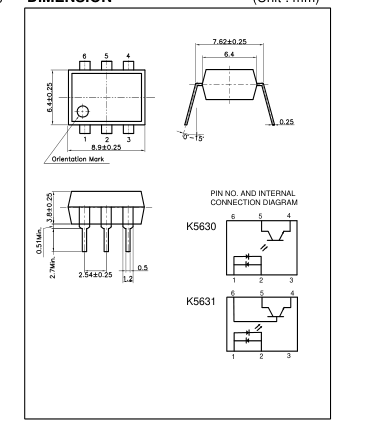
Diodes and a Silicon NPN Phototransistor in a 6-pin package.
FEATURES
- Switching Time - Type 3㎲
- Collector-Emitter Voltage : Min.35V
- Current Transfer Ratio : Typ.10% (at IF= 10mA, VCE=10V)
- Electrical Isolation Voltage : AC5000Vrms
- Without Base Connection - K5630
- With Base Connection - K5631
- UL Recognized File No. E107486
APPLICATIONS
- Interface between two circuits of different potential
- AC signal input
- Telephone set & line interface
- I/O compatible with integrated circuits
MAXIMUM RATINGS
(Ta=25℃ )
| Parameter | Symbol | Rating | Unit | |
|---|---|---|---|---|
| Input | Forward Current | IF | ± 60 | mA |
| *1 Peak Forward Current | IFP | ± 1 | A | |
| Power Dissipation | PD | 70 | mW | |
| Output | Collector-Emitter Breakdown Voltage | BVCEO | 35 | V |
| Emitter-Collector Breakdown Voltage | BVECO | 6 | V | |
| Collector-Base Breakdown Voltage** | BVCBO | 70 | V | |
| Emitter-Base Breakdown Voltage** | BVEBO | 6 | V | |
| Collector Current | IC | 50 | mA | |
| Collector Power Dissipation | PC | 150 | mW | |
| *2 Input to Output Isolation Voltage | Viso | AC5000 | Vrms | |
| Storage Temperature | Tstg | -55~+125 | ℃ | |
| Operating Temperature | Topr | -30~+100 | ℃ | |
| *3 Lead Soldering Temperature | Tsol | 260 | ℃ | |
| Total Power Dissipation | Ptot | 200 | mW | |
\*\* Except for K5630 \*1. Input current with 100㎲ pulse width, 1% duty cycle \*2. Measured at RH=40~60% for 1min \*3. 1/16 inch form case for 10sec
1/3
Page 2
K5630 • K5631
ELECTRO-OPTICAL CHARACTERISTICS
(Ta=25℃ , unless otherwise noted)
| Parameter | Symbol | Condition | Min. | Typ. | Max. | Unit. | |
|---|---|---|---|---|---|---|---|
| Input | Forward Voltage | VF | IF= 10mA | - | 1.15 | 1.30 | V |
| Capacitance | CT | V=0, f=1MHz | - | 30 | - | pF | |
| Output | Collector-Emitter Breakdown Voltage | BVCEO | IC=1mA | 35 | - | - | V |
| Emitter-Collector Breakdown Voltage | BVECO | IE=0.1mA | 6 | - | - | V | |
| Collector-Base Breakdown Voltage ** | BVCBO | I =0.1mA C | 70 | - | - | V | |
| Emitter-Base Breakdown Voltage ** | BVEBO | I =0.1mA C | 6 | - | - | V | |
| Collector Dark Current | ICEO | IF=0, VCE=10V | - | - | 100 | nA | |
| Capacitance | CCE | VCE=0, f=10MHz | - | 10 | - | pF | |
| Coupled | *4 Current Transfer Ratio | CTR | IF= 10mA, VCE=10V | 50 | - | 200 | % |
| Collector-Emitter Saturation Voltage | VCE(SAT) | IF= 10mA, IC=0.5mA | - | - | 0.4 | V | |
| Input-Output Capacitance | CIO | V=0, f=1MHz | - | 2 | - | pF | |
| Input-Output Isolation Resistance | RIO | RH=40~60%, V=500V | - | 1011 | - | Ω | |
| Rise Time | tr | VCE=5V, RL=100 IC=2mA | - | 3 | - | ㎲ | |
| Fall Time | tf | - | 3 | - | ㎲ | ||
| CTR Symmetry | CTR1/CTR2 | 0.33 | - | 3.0 | |||
\*\* Except for K5630 \*4. CTR=(IC/IF) X 100 (%)
2/3
Page 3
K5630 • K5631
Forward Current vs.
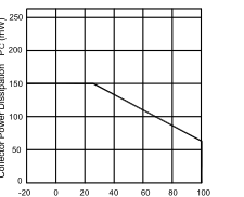
Collector Power Dissipation vs.
Ambient Temperature
Ambient Temperature
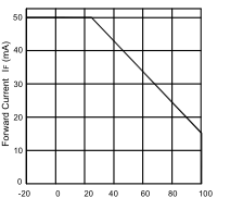
Ambient Temperature Ta (℃ )
Ambient Temperature Ta (℃ )
Collector Current vs.
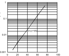
Dark Current vs.
Collector-Emitter Voltage
Ambient Temperature
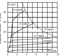
Collector-Emitter Voltage VCE (V)
Ambient Temperature Ta (℃ )
Collector Current vs.
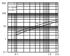
Response Time vs.
Forward Current
Load Resistance
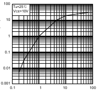
Forward Current IF (mA)
Load Resistance RL (㏀)
3/3
Forward Current vs. Forward Voltage
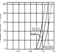
Forward Voltage VF (V)
Collector Current vs. Ambient Temperature
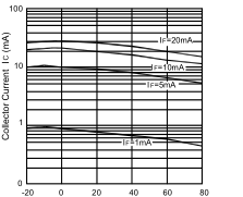
Ambient Temperature Ta (℃ )
Switching Time Test Circuit
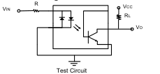
Input
Output 10%
90% tr tf
Waveform