
 Download PDF
K150B001UP SCHNEIDER
Document overview
- PDF pages: 10
Technical content
Page 1
Specifications
cam changeover switch - 1-pole -
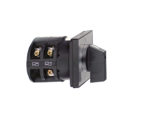
60° - 150 A - front mounting
Product availability : Non-Stock - Not normally stocked in distribution facility
Price\* : 752.00 USD
Main
Harmony K
Range of Product
Complete cam switch
Product or Component Type
K150
Component name
150 A
[Ith] conventional free air thermal current
Front
Mounting Location
4 holes
Fixing Mode
With front plate 88 x 88 mm
Cam switch head type
handle
Type of operator
Without
Rotary handle padlocking
With metallic, 1 - 0 - 2 black
Presentation of legend
Changeover switch
Cam switch function
Without
Return
With Off position
Off position
1P
Poles description
Right: 0° - 60°
Switching positions
Left: 0° - 300°
IP40 IEC 529
IP degree of protection
IP40 NF C 20-010
Complementary
60 °
Switching angle
690 V 3)EN 60947-1
[Ui] rated insulation voltage
690 V 3)IEC 60947-1
25000 A
Short-circuit current
200 A cartridge fuse gG
Short-circuit protection
[Uimp] rated impulse withstand 6 kV EN 947-1
6 kV IEC 947-1
voltage
Slow-break
Contact operation
With
Positive opening
Captive screw clamp terminals flexible 1 x 50 mm²
Electrical connection

Page 2
Captive screw clamp terminals solid 1 x 70 mm²
22.13 lbf.in (2.5 N.m)
Tightening torque
150000 mA DC 140 V 3 resistive 1 ms)
Switching capacity in mA
150000 mA DC 24 V 1 inductive 50 ms) 150000 mA DC 24 V 1 resistive 1 ms) 150000 mA DC 48 V 1 resistive 1 ms) 150000 mA DC 48 V 2 inductive 50 ms) 150000 mA DC 48 V 2 resistive 1 ms) 150000 mA DC 70 V 3 inductive 50 ms) 150000 mA DC 70 V 3 resistive 1 ms) 150000 mA DC 95 V 2 resistive 1 ms) 50000 mA DC 30 V 1 inductive 50 ms) 50000 mA DC 60 V 2 inductive 50 ms) 50000 mA DC 90 V 3 inductive 50 ms)
300000 cycles
Mechanical durability
1.74 lb(US) (0.79 kg)
Net Weight
Environment
EN/IEC 60947-3
Standards
CULus 240 V 15 hp 1 phase
Product certifications
CULus 240 V 25 hp 3 phase CULus 480 V 40 hp 3 phase CULus 120 V 7.5 hp 1 phase
TC
Protective treatment
-13…131 °F (-25…55 °C)
Ambient air temperature for operation
-40…158 °F (-40…70 °C)
Ambient Air Temperature for Storage
Class II IEC 60536
Overvoltage category
Class II NF C 20-030
Ordering and shipping details
21446 - 9003 K CAM SWITCHES
Category
CS1
Discount Schedule
3389118091290
GTIN
1
Nbr. of units in pkg.
22.08 oz (626 g)
Package weight(Lbs)
No
Returnability
AT
Country of origin
Packing Units
PCE
Unit Type of Package 1
3.94 in (10 cm)
Package 1 Height
3.94 in (10 cm)
Package 1 width
6.69 in (17 cm)
Package 1 Length
S03
Unit Type of Package 2
5
Number of Units in Package 2
8.08 lb(US) (3.664 kg)
Package 2 Weight
11.81 in (30 cm)
Package 2 Height
11.81 in (30 cm)
Package 2 width
15.75 in (40 cm)
Package 2 Length
Page 3
Offer Sustainability
WARNING: This product can expose you to chemicals including: Nickel compounds, which is known
California proposition 65
to the State of California to cause cancer, and Di-isodecyl phthalate (DIDP), which is known to the State of California to cause birth defects or other reproductive harm. For more information go to www.P65Warnings.ca.gov
REACh Regulation
REACh Declaration
Yes
REACh free of SVHC
Pro-active compliance (Product out of EU RoHS legal scope)
EU RoHS Directive
EU RoHS Declaration
Yes
Toxic heavy metal free
Yes
Mercury free
RoHS exemption information
Yes
China RoHS Regulation
China RoHS declaration
The product must be disposed on European Union markets following specific waste collection and
WEEE
never end up in rubbish bins.
Contractual warranty
18 months
Warranty
Page 4
Dimensions Drawings
Dimensions
Front Mounting
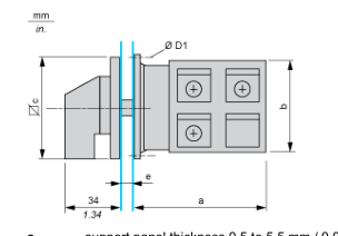
support panel thickness 0.5 to 5.5 mm / 0.02 to 0.22 in in. e

in.
0.21
Page 5
Mounting and Clearance
Panel Cut-Out
Front Mounting
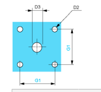
| D2 | D3 | G1 | |||
| mm | in. | mm | in. | mm | in. |
| 6 | 0.24 | 13 | 0.51 | 68 | 2.68 |
Page 6
Link Positions (Factory Mounted)
Diagram for 1 to 4-pole Switches Select the number of poles according to the product characteristics
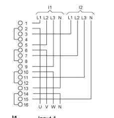
Input 1 I1 Input 2 I2
Page 7
Marking
Page 8
Angular Position of Switch
Page 9
Switching Program
1-pole (1) 2-pole (2) 3-pole (3) 4-pole (4)
Page 10
Convention Used for Switching Program Representation
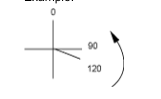
Contact closed Contact closed in 2 positions and maintained between the 2 positions Sealed assembly for auto-maintain control Overlapping contacts Spring return position: for a switching angle of 90°, spring return is over 30° after the last position (for a maximum of 3 simultaneous contacts). Example: