
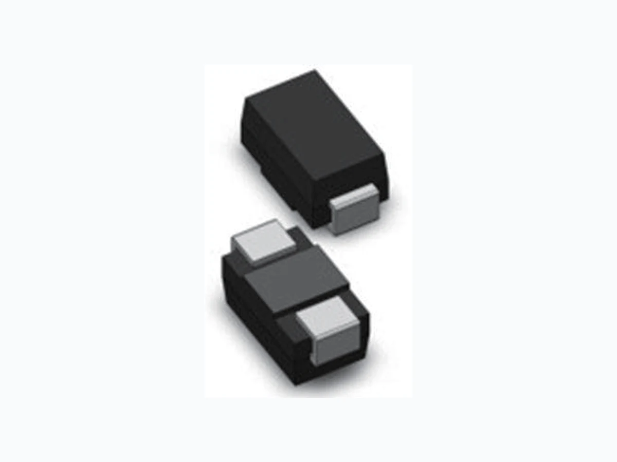

 Download PDF
KXXXXSA UNSEMI
Document overview
- PDF pages: 5
Technical content
Page 1
ROHS
Sidac
Description
The sidac is a silicon bilateral voltage triggered switch with greater power-handling capabilities than standard diacs. Upon application of a voltage exceeding the sidac breakover voltage point, the sidac switches on through a negative
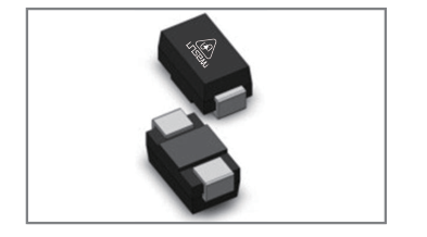
resistance region to a low on-state voltage. Conduction continues until the current is interrupted or drops below the minimum holding current of the device.
Features
Excellent capability of absorbing transient surge Quick response to surge voltage (ns Level) Glass passivated junctions High voltage lcmp ignitors
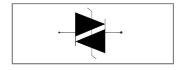
Functional Diagram
Applications
High-voltage lamp ignitors Natural gas ignitors Gas oil ignitors High-voltage power supplies Xenon ignitors Over voltage protector Pulse generators Fluorescent lighting ignitors HID lighting ignitors
Maximum Characteristics (TA=25℃ RH=45%-75% ,unless otherwise noted)
| Parameter | Symbol | Value | Unit |
|---|---|---|---|
| Maximum surge on-state current non-repetitive one cycle peak value(50Hz) | ITSM | 16.7 | A |
| Critical rate-of-rise of on-state current | diT/dt | 80 | A |
| On-state RMS Current | IT | 1 | A |
| Storage temperature range | TSTG | - 40 to +125 | °C |
| Operating junction temperature range | TJ | - 40 to +125 | °C |
1/4
Page 2
Sidac
ROHS
Electrical Characteristics (@=25℃ unless otherwise Specified)
| Part Number | VDRM @ IDRM | VBO | IBO | VT@ IT=1A | RS | IH | Body Marking | ||
|---|---|---|---|---|---|---|---|---|---|
| V μA | V | μA | V | KΩ | mA | ||||
| Min | Max | Min | Max | Max | Max | Min | Min | ||
| K0900SA | 70 | 1 | 80 | 97 | 50 | 2 | 0.1 | 10 | K09S |
| K1050SA | 90 | 1 | 95 | 113 | 50 | 2 | 0.1 | 10 | K10S |
| K1200SA | 100 | 1 | 110 | 125 | 50 | 2 | 0.1 | 10 | K12S |
| K1300SA | 110 | 1 | 120 | 138 | 50 | 2 | 0.1 | 10 | K13S |
| K1400SA | 120 | 1 | 130 | 146 | 50 | 2 | 0.1 | 10 | K14S |
| K1500SA | 130 | 1 | 140 | 170 | 50 | 2 | 0.1 | 10 | K15S |
| K1800SA | 160 | 1 | 170 | 195 | 50 | 2 | 0.1 | 10 | K18S |
| K2000SA | 180 | 1 | 190 | 215 | 50 | 2 | 0.1 | 10 | K20S |
| K2200SA | 190 | 1 | 205 | 230 | 50 | 2 | 0.1 | 10 | K22S |
| K2400SA | 200 | 1 | 220 | 250 | 50 | 2 | 0.1 | 10 | K24S |
| K2600SA | 220 | 1 | 240 | 270 | 50 | 2 | 0.1 | 10 | K26S |
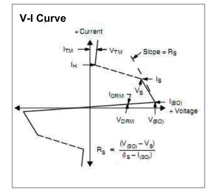
Electrical Characteristics (@=25℃ unless otherwise Specified)
| Parameter | Symbol |
|---|---|
| Peak off-state voltage | VDRM |
| Off-state current | IDRM |
| Switching voltage | VS |
| Switching current | IS |
| Switching resistance | RS |
| On-state voltage | VT |
| Holding current | IH |
| Break over Voltage | VBO |
| Break over current | IBO |
2/4
Page 3
Sidac
ROHS
Electrical Characteristics (@=25℃ unless otherwise Specified)
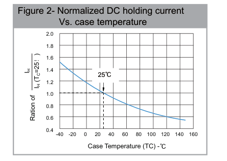
Soldering Parameters
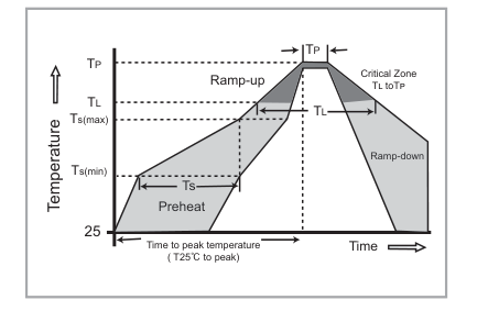
| Reflow Condition | Lead–free assembly | |
|---|---|---|
| Pre Heat | -Temperature Min (Ts(min)) | 150°C |
| -Temperature Max (Ts(max)) | 200°C | |
| - Time (min to max) (TS) | 60 -180 Seconds | |
| Average ramp up rate ( Liquidus Temp TL) to peak | 3°C/Second max | |
| TS(max) to TL - Ramp-up Rate | 3°C/Second max | |
| Reflow | - Temperature (TL) (Liquidus) | 217°C |
| - Time (min to max) (TS) | 60 -150 Seconds | |
| Peak Temperature (TP) | 260 +0/-5°C | |
| Time within 5°C of actual peak Temperature (TP) | 8-15 Seconds | |
| Ramp-down Rate | 6°C/Second Max | |
| Time 25°C to peak Temperature (TP) | 8 minutes Max | |
| Do not exceed | 260°C | |
3/4
Page 4
Sidac
ROHS
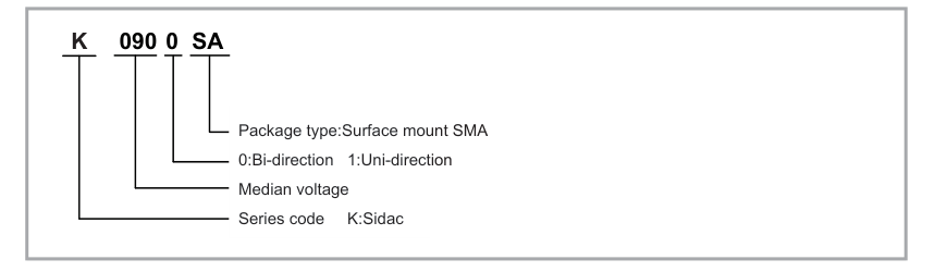
Ordering Information
Package Mechanical Data
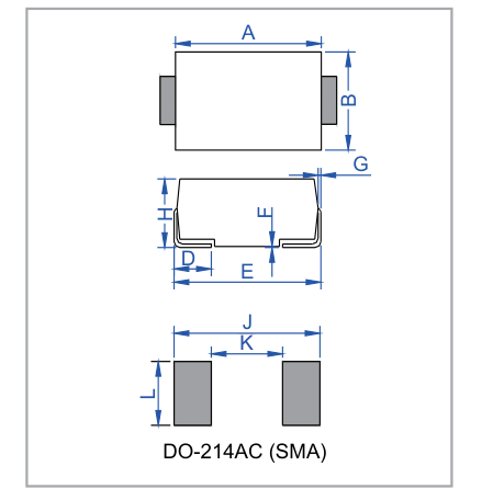
| Dimensions | Inches | Millimeters | ||
| Min | Max | Min | Max | |
| A | 0.167 | 0.183 | 4.25 | 4.65 |
| B | 0.098 | 0.114 | 2.50 | 2.90 |
| C | 0.053 | 0.065 | 1.35 | 1.65 |
| D | 0.030 | 0.060 | 0.76 | 1.52 |
| E | 0.194 | 0.208 | 4.93 | 5.28 |
| F | 0.002 | 0.008 | 0.051 | 0.203 |
| G | 0.006 | 0.012 | 0.15 | 0.31 |
| H | 0.078 | 0.095 | 1.98 | 2.41 |
| J | 0.256 | -- | 6.50 | -- |
| K | -- | 0.090 | -- | 2.30 |
| L | 0.067 | -- | 1.70 | -- |
Tape And Reel Specification
| Part Number | Component Package | Reel (PCS) | Per carton(PCS) |
|---|---|---|---|
| KxxxxSA | DO214AC/SMA | 5,000 | 80,000 |
4/4
Page 5
ROHS
ROHS
Disclaimer
UNSEMI RESERVES THE RIGHT TO MAKE CHANGE ON OUR PRODUTS , PRODUCTS SPECIFICATION
AND DATA WITHOUT NOTICE TO IMPROVE RELIABILITY, FUNCTION OR DESIGN OR OTHERWISE.
UN SEMICONDUCTOR LIMITED its affiliates, agents, and employees, and all persons acting on its or their
behalf (collectively, “UNSEMI”)does not give any representations or warranties for any errors, inaccuracies or
incompleteness contained in any datasheet or in any other disclosure relating to any product.
In no event shall UNSEMI be liable for any indirect, incidental, punitive, special or consequential damages
(including any and all implied warranties, warranties of fitness for particular purpose, non-infringement and
merchantability.) whether or not such damages are based on tort (including negligence), warranty, breach of
contract or any other legal theory.
Statements regarding the suitability of products for certain types of applications are based on UNSEMI
knowledge of typical requirements that are often placed on UNSEMI products in generic applications. Such
statements are not binding, statements about the suitability of products for a particular application. It is the
customer's responsibility to validate that a particular product with the properties described in the product
specification is suitable for use in a particular application. Parameters provided in datasheets or specifications
may vary in different applications and performance may vary over time. All operating parameters, including typical
parameters, must be validated for each customer application by the customer's technical experts. Product
specifications do not expand or otherwise modify UNSEMI's terms and conditions of purchase, including but not
limited to the warranty expressed therein.
Unless otherwise agreed in writing, UNSEMI product is not designed, authorized or warranted to be suitable for
use in medical life-saving, or life-sustaining application , nor in applications where failure or malfunction of a
UNSEMI product can reasonably be expected to result in personal injury, death or severe property or environmental
damage. UNSEMI and its suppliers accept no liability for inclusion or use of UNSEMI products in such equipment or
applications and therefore such inclusion and/or use is at the customer's own risk.
All referenced brands, product names, service names and trademarks are the property of their respective owners.