
DATASHEET SEARCH SITE
Document overview
- Manufacturer or author: Provided By www.digicamel.com(FREE DATASHEET DOWNLOAD SITE)
- PDF pages: 10
Technical content
- Sealed IP 68 (mated connectors)
- Mechanically keyed : ensures correct polarization and alignment.
- Contact arrangements : from 2 to 10 contacts.
- Wire gauge range from 28 AWG to 14 AWG.
- High contact density in a small space.
- Contact termination in either crimp, solder or PCB contacts. Part number system MS D SCM05G1FDJKXBasic series Shell configuration FD - ER - EP - PC Size 0 - 1 Keying G Contact type M : pin F : socket (in relation with keying) Contact termination C : crimp ; S : solder ; P* : straight PCB tails ; Q* : 90° PCB tails ; W : 0.7 mm clipped solder Material & surface plating S : Outer shell in brass alloy with glossy chrome over nickel N : Outer shell in brass alloy with black plating (consult us) D : Obligatory suffix S : Insulator in PPS P : Insulator in Peek (for Ø 0.5 mm contacts only) Obligatory suffix for layouts including contacts of Ø 0.5 mm Options M : Connector with backnut for protective boot (protective boot to order separately page 34) G : Connector adapted to accomodate larger cables (Ø 4.5 to 6 in size 0 and Ø 6 to 8 in size 1) R : Red dot (possible for FD, PC, ER only) * For receptacles with female contacts only. Key features User advantages Temporary immersion IP 68 6-collet cluster Allows a wide range of cable diameter applications for a single connector. Reduces inventory variations. Removable contacts Crimp versions allow easier wiring and maintenance. JKX Series
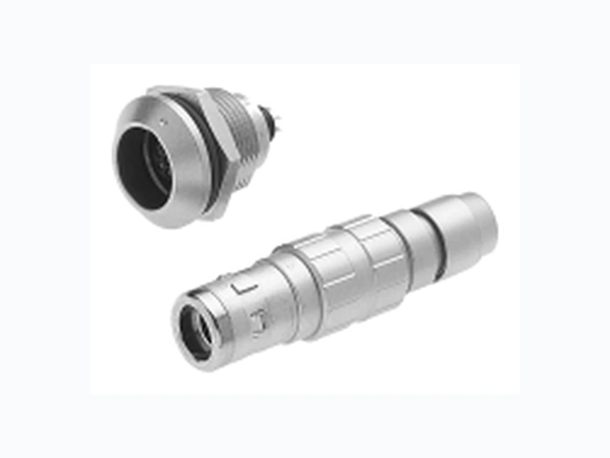
- Available JKX shells
- Dimensions FD : Straight plug with cable clamping Size A Ø B Ø M 1.5 to 4.5 2 to 6 ER : Fixed receptacle, front panel mounting Size A 19.5 24.5 B 4.5 8.5 C 4.5 Ø D EP : Fixed receptacle, back panel mounting Size A 19.5 24.5 B 4.5 C 3.2 Ø D PC : Cable mounted receptacle
- Option G : to accomodate bigger cables Size A Ø B Ø M 4.6 to 6 6 to 8 Size A Ø B Ø C 2 to 6
- Multi contacts inserts G keying is available in standard version (0° keying angle, plugs with pin contacts, receptacles with female contacts) for the 4 shell types. Reverse gender available in all layouts. Shell size Key ER EP PC FD
0 G GG _ G
1 G GGGG
G Concerning the availability of other alternatives, please consult our commercial office. Male AWG Max. Testing Working Shell insulator Contact S C P* Q* Ø Solder Crimp current voltage voltage size viewed from layout solder crimp straight 90° Contact wire wire rating (Vdc / wiring side PCB tails PCB tails Max. Max. (A) (Vrms) Vrms) 02 S C P Q 0.9 24 20 10 1400 660/460 03 S C P Q 0.9 24 20 8 1300 600/420 04 S C P Q 0.7 26 22 7 1400 660/460 05 S C P Q 0.7 26 22 6.5 800 400/260 06 S P 0.5 28 - 2.5 680 320/220 07 S P 0.5 28 - 2.5 680 320/220 02 S C P 1.3 20 18 15 1600 760/530 03 S C P Q 1.3 20 18 12 1300 600/420 04 S C P Q 0.9 24 20 10 1900 900/630 05 S C P Q 0.9 24 20 9 1400 660/460 06 S C P Q 0.7 26 22 7 1400 660/460 07 S C P Q 0.7 26 22 7 1400 660/460 08 S C P Q 0.7 26 22 5 1200 600/420 10 S P 0.5 28 - 2.5 600 300/200 Inserts with fixed contacts (non removable contacts) * For receptacles with female contacts only Available Contact types JKX Series
- Protective boot Protective boot can accept multiple cable diameters
- Caps : an efficient protection until 2 bars With each JKX connector, one protective boot can accept diverse cable diameters thus the end-user can manage various cable diameters without bothering with multiple part numbers. Material : ELASTOLLAN (PUR) Working temperature : - 40°C ; + 80°C - 40°F ; + 176°F DimensionsPart Shell Shell size number size Option Ø AL Ø Câble G min Max. JBX 0 MP* 0 - 2.2 20 1.5 5.5 JBX 1 MP* 1 0 2.6 25 2 7.5 JBX 2 MP* - 1 4 30 3.5 9.7 Color code Colors A blue B white G grey J yellow M brown N black R red V green O orange * Color code Part number Ø JKX BR0 15 JKX BR1 17
- Material and treatment
- Mechanical and climatics Component Material Standard Surface treatment (µm) ISO ASTM Cr Ni Au Outer shell and collet nut Brass CuZn40Pb3 C38500/C360 0.1 - 0.6 5 - 8 - Latching sleeve & metal collet Brass CuZn40Pb3 C38500/C360 - 5 - 8 - Shielding ring Brass CuZn40Pb3 C38500/C360 - 3 - 7 - Nut Brass CuZn40Pb3 C38500/C360 5 - 8 - Tapered washer and half bushes Brass CuZn40Pb3 C38500/C360 - 5 - 8 - Socket contact (1) Copper-nickel CuNi1Pb1P CDA C 19150 - 3 - 5 0.5 Pin contact (1) Brass CuZn35Pb2 C35300/C360 - 3 - 5 0.5 Clip Beryllium copper CuBe1,9 C17200/C360 - - - Component Material Color Temperature withstanding Insert PPS + 40%GF black - 65°C + 200°C - 85°F + 392°F or PEEK + 15%GF brown - 50°C + 250°C - 58°F + 482°F Plastic collet PA 6/6 + MoS2 black - 55°C + 125°C - 67°F + 257°F Cable seal Silicon rubber red - 50°C + 250°C - 58°F + 482°F Characteristics Values Standard Method Endurance > 1000 cycles (except for 0.7 mm crimp contacts for which MIL-STD 2016.1endurance is limited to 500 cycles) 1344A Protection index IP 68 (watertight - 48 hours under 1 m of water) CEI 529 - 55°C + 125°Cwith plastic collets - 67°F + 257°F -- Operating temperature with optional metal collets - 55°C + 200°C - 67°F + 392°F - - (1) Gold thickness as per MIL-G-45204C type 1, class 00. JKX Series
Wiring and assembly instructions
- Panel cutout
- Removable contacts Crimp contacts Solder contacts Contact Usable cables Max. Contact Endurance Core section (mm2) current resistance (number Ø C Ø F AWG rating (A) (m Ω ) of cycles)min Max. 1.3 1.4 0.326 0.823 18 - 20 - 22 15 3 > 1000 Contact Usable cables Max. Contact Endurance Core section (mm2) current resistance (number Ø C Ø F AWG rating (A) (m Ω ) of cycles)min Max. 0.9 0.8 - 0.21 24 10 3.5 > 1000 1.3 1.1 - 0.60 20 15 3 > 1000 The conductor bucket on the solder contacts is designed with an angle to form a cup into which the solder can flow easily.
- Fixed contacts Solder contacts Contact Usable cables Max. Contact Endurance Shell Core section current resistance (number Ø C Ø F size (mm2) Max. AWG rating (A) (m Ω ) of cycles) 0.5 0.5 0 - 1 0.096 28 5 10 > 1000 0.7 0.63 0 - 1 0.15 26 7 5 > 1000 Contacts for PCB Size 0 1 Ø A 14.1 16.1 B 12.6 14.6 Contacts for PCB Contact length dimensions “L” PCB tail length size 0 dimension “L” 5.5 mm 0.7 mm female PCB tail length size 0 dimension “L” 3.5 mm 0.7 mm female PCB tail length size 1 dimension “L” 4.0 mm 0.9 mm female PCB tail length size 0 dimension “L” 3.5 mm 0.9 mm female PCB tail length size 1 dimension “L” 4.0 mm 1.3 mm female PCB tail length size 1 dimension “L” 4.0 mm, dimension “F” 0.7 mm B A +0.2 ø+0.3 +0.1 0.7 1.0 - 0.3 22 7 5 500 Max.
≤ 1.35 > 1.35 ≤ 1.6 > 1.6 ≤ 1.35 > 1.35 ≤ 1.6 > 1.6 ≤ 2.1 > 2.1 Wiring and assembly instructions
- Cable stripping for connectors with crimp contacts
- Cable stripping for connectors with solder contacts Stripping for FD / PC LCT 0.7 15 7 0.9 15 7 0.7 17 8 1 0.9 17 8 1.3 17 8 Shell size Ø Contacts Ø I Shell size Ø Contacts 5.5 5.5 5.5 5.5 5.5 Stripping for FD / PC LST 0.5 11 2 7 0.7 12 3 7 0.9 12 3 7 0.5 13 2 8 0.7 14 3 8 0.9 14 3 8 1.3 14 3.5 8 ØI : diameter over insulation ➀ : O’ring for sealing between receptacle and plug shell ➁ : O’ring for sealing between receptacle and panel ➂ : O’ring for sealing between plug body and backshell ➃ : seals to accomodate variety of cable diameters Fixed receptacle Straight plug
- Watertightness design (mated connectors) JKX Series
- Connector preparation 1 - Select the proper collet ➃ and the cable seal ➂ (see page 39). 2 - Slide protective boot ➅ , the backnut ➄ , the collet ➃ , the cable seal ➂ , the outershell ➁ and the taper seat ➀ onto the cable.Strip end of cable (see pg. 16)
- Contacts wiring : crimp contacts 1 - Select the proper crimping tool (see page 48) 2 - Adjust the crimping tool based on the wire size “AWG”. (See wire size and crimp tool settings on the back of this locator.) 3 - Crimp the contacts ➃ then insert the contact into the insulator until the clip is fully seated and cannot be removed.
- Contacts wiring : solder contacts Fixed solder contacts 0.5 mm and 0.7 mm Removable solder contacts from 0.9 mm to 1.3 mm 1 - Insert wire into solder cup and solder 1 - Insert wire into solder cup and solder 2 - Insert the contact into the insulator until the clip is fully seated and cannot be removed.
- Connector assembly 1 - In case of shielded cable, comb out the shield and fold back over the tapper seat ➀ . 2 - Position 2 half bushes ➈ , making sure that the insert key appears through the windows of one bush. 3 - Position the taper seat ➀ on the half bushes ➈ . 4 - Position all the sub-assembly in connector housing ➉ , making sure to keep the sub- assembly well aligned. 5 - Screw the outershell ➁ following the torque values on page 39. Install the cable seal ➂ and the collet ➃ into the outershell ➁ then screw the backnut ➄ till bottoming. Use 2 wrenches well positionned on the flats A and B. Place a wrench to grip flats B, use the other wrench to tighten the backnut at the flats A following the torque values on page 39. 6 - Install the protective boot ➅ if applicable. Wiring and assembly instructions : STRAIGHT PLUG
- Cable stripping : see page 37
- Collets selection according to cable diameters 3 or 5 collets per shell size allow a wide range of cable diameters for a single connector. Cable out diameters are for information only, since values will change with each cable construction. Cable diameter Shell size 0 Size 0, option G Shell size 1 Size 1, option G Collet number 4 in shell size 0 and collet number 6 in shell size 1 are not used. Discreet application based on cable diameter• Cable seal selections according to cable size Collet number Cable diameter Shell size 0 Size 0, option G Shell size 1 Size 1, option G 2 1.5 - 2.9 3.5 3 - 4.5 2.5 2 - 3.4 - 5.5 5 - 6 5 - 6 6.1 - 6.4 7 6.5 - 8 Cable gland Ø A Advised torque* in Nm 0 0 (option G) 1 1 (option G) 1.6 / 1.8 / 1.5 2.5 0.8 1 0.8 1 Size mm 14 x 1 16 x 1 0 0 (option G) 1 1 (option G) 81 3 10 11 12 14 Size Tools (jaw dimensions) Wiring and assembly instructions
- Coupling torques Tool dimensions Torque values are the maximum allowable for each connector size. Torque values will vary due to the type and size of the cable used *Apply thread lock to back nut prior to assembly. Tool numbers can be found on page 32
- Shielding Tested according to MIL-STD 1344 A, method 3007 Shell size 0 4 1 3 G AmV Ø A Electrical continuity (mΩ ) JKX Series
- Sealed IP 67 (mated connectors)(FE, EC, SE, & PC)
- Watertight receptacles IP68 (HC & HH)
- Mechanically keyed : ensure correct polarisation and alignment.
- Contact arrangements : from 2 to 19 contacts.
- Wire gauge range from 26 AWG to 12 AWG.
- High contact density in a small space.
- Contact termination in either crimp, solder or PCB contacts. Part number system RS D SCM12G2FEJBXBasic series Shell type FE-HH-HC-EC-PE-SE Shell size 2 Keying G Contact type M : pin F : socket (in relation with keying) Contact termination C : crimp ; S : solder ; P* : straight PCB tails ; Q* : 90° PCB tails Material & surface plating S : Outer shell in brass alloy with chrome over nickel N : Outer shell in brass alloy with black plating (consult us) D : Obligatory suffix S : Obligatory suffix Option R : FE, PE, HH, & HC N/A for EC & SE * For receptacles with female contacts only. User advantages Wet environment IP67 6-collet cluster Allows a wide range of cable diameter applications for a single connector. Reduces inventory variations. Removable contacts (EC, FE, SE & PE) Crimp versions allow easier wiring and maintenance.