
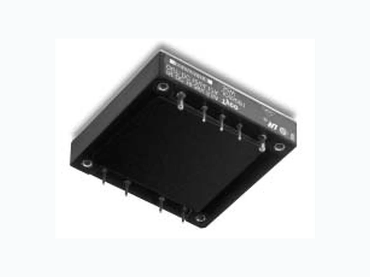
JC050B ETC1
Document overview
- Manufacturer or author: Provided By www.digicamel.com(FREE DATASHEET DOWNLOAD SITE)
- PDF pages: 16
Technical content
Features
■ Small size: 61.0 mm x 57.9 mm x 13.1 mm ■ High power density ■ High efficiency: 85% typical ■ Low output noise ■ Constant frequency ■ Industry-standard pinout ■ Metal baseplate ■ 2:1 input voltage range ■ Overtemperature protection (100 W only) ■ Remote sense ■ Remote on/off ■ Adjustable output voltage ■ Case ground pin ■ UL* Recognized, CSA† Certified, VDE Licensed * UL is a registered trademark of Underwriters Laboratories, Inc. † CSA is a registered trademark of Canadian Standards Assn.
Description
The JC050B, JC075B, JC100B Power Modules are dc-dc converters that operate over an input voltage range of 18 Vdc to 36 Vdc and provide a precisely regulated dc output. The outputs are fully isolated from the inputs, allow- ing versatile polarity configurations and grounding connections. The modules have maximum power ratings from 50 W to 100 W at typical full-load efficiency of 85%. The sealed modules offer metal baseplate for excellent thermal performance. Threaded-through holes are pro- vided to allow easy mounting or addition of a heat sink for high-temperature applications. The standard feature set includes remote sensing, output trim, and remote on/off for convenient flexibility in distributed power applications.
periods can adversely affect device reliability. Table 1. Input Specifications CAUTION: This power module is not internally fused. An input line fuse must always be used. safety agencies require a normal-blow, dc f use with a maximum rating of 20 A (see Safety Considerations section). type of fuse with a lower rating can be used. Refer to the fuse manufacturer’s data for further information.
Table 2. Output Specifications Table 3. Isolation Specifications
4 Tyco Electronics Corp. Data Sheet October 199718 Vdc to 36 Vdc Input, 12 Vdc Output; 50 W to 100 W JC050B, JC075B, JC100B Power Modules: dc-dc Converters; General Specifications Feature Specifications Unless otherwise indicated, specifications apply over all operating input voltage, resistive load, and temperature conditions. See Feature Descriptions for additional information. Parameter Min Typ Max Unit Calculated MTBF (I O = 80% of IO, max; TC = 40 °C) 2,600,000 hr. Weight — — 100 (3.5) g (oz.) Parameter Symbol Min Typ Max Unit Remote On/Off Signal Interface (VI = 0 V to 36 V; open collector or equivalent compatible; signal referenced to VI(–) terminal; see Figure 14 and Feature Descriptions.): JCxxxB1 Preferred Logic: Logic Low—Module On Logic High—Module Off JCxxxB Optional Logic Logic Low—Module Off Logic High—Module On Logic Low: At Ion/off = 1.0 mA At Von/off = 0.0 V Logic High: At Ion/off = 0.0 µA At Von/off = 15 V Turn-on Time (See Figure 10) (IO = 80% of IO, max; VO within ±1% of steady state) Von/off Ion/off Von/off Ion/off 1.2 1.0 V mA V µA ms Output Voltage Adjustment (See Feature Descriptions.): Output Voltage Remote-sense Range Output Voltage Set-point Adjustment Range (trim) 1.2 110 V %VO, nom Output Overvoltage Clamp V O, clamp 13.2 — 16.0 V Overtemperature Shutdown (100 W only; see Feature Descriptions.) Tc — 105 — °C
18 Vdc to 36 Vdc Input, 12 Vdc Output; 50 W to 100 W
Figure 5. Typical JC075B Output Characteristics at Figure 6. Typical JC100B Output Characteristics at Figure 7. Typical JC050B Converter Efficiency vs. Figure 8. Typical JC075B Converter Efficiency vs.
88 Tyco Electronics Corp. JC050B, JC075B, JC100B Power Modules: dc-dc Converters; Test Configurations (continued) 8-749 (C) Note: All measurements are taken at the module terminals. When socketing, place Kelvin connections at module terminals to avoid measurement errors due to socket contact resistance.Figure 13. Output Voltage and Efficiency Measurement Test Setup Design Considerations Input Source Impedance The power module should be connected to a low ac-impedance input source. Highly inductive source impedances can affect the stability of the power mod- ule. For the test configuration in Figure 11, a 33 µF electrolytic capacitor (ESR < 0.7 Ω at 100 kHz) mounted close to the power module helps ensure sta- bility of the unit. For other highly inductive source impedances, consult the factory for further application guidelines. Safety Considerations For safety-agency approval of the system in which the power module is used, the power module must be installed in compliance with the spacing and separation requirements of the end-use safety agency standard, i.e., UL-1950, CSA 22.2-950, and EN60950. For the converter output to be considered meeting the requirements of safety extra-low voltage (SELV), the input must meet SELV requirements. If the input meets extra-low voltage (ELV) require- ments, then the converter’s output is considered ELV. The input to these units is to be provided with a maxi- mum 20 A normal-blow fuse in the ungrounded lead. Electrical Descriptions Current Limit To provide protection in a fault (output overload) condi- tion, the unit is equipped with internal current-limiting circuitry and can endure current limiting for an unlim- ited duration. At the point of current-limit inception, the unit shifts from voltage control to current control. If the output voltage is pulled very low during a severe fault, the current-limit circuit can exhibit either foldback or tai- lout characteristics (output current decrease or increase). The unit operates normally once the output current is brought back into its specified range. Feature Descriptions Remote On/Off Two remote on/off options are available. Positive logic remote on/off turns the module on during a logic-high voltage on the ON/OFF pin, and off during a logic low. Negative logic remote on/off turns the m odule off dur- ing a logic high and on during a logic low. Negative logic (code suffix “1”) is the factory-preferred configura- tion. To turn the power module on and off, the user must supply a switch to control the voltage between the on/off terminal and the V I(-) terminal (Von/off). The switch can be an open collector or equivalent (see Figure 14). A logic low is V on/off = 0 V to 1.2 V. The max- imum Ion/off during a logic low is 1 mA. The switch should maintain a logic-low voltage while sinking 1 mA. During a logic high, the maximum V on/off generated by the power module is 15 V. The maximum allowable leakage current of the switch at V on/off = 15 V is 50 µA. If not using the remote on/off feature, do one of the fol- lowing: ■ For negative logic, short ON/OFF pin to V I(-) ■ For positive logic, leave ON/OFF pin open. VI (+) I I I O SUPPL Y CONTACT RESISTANCE CONTACT AND DISTRIBUTION LOSSES LOAD SENSE(+) VI (–) VO(+) VO(–) SENSE(–) η [Vo(+) – Vo(-)]Io 100×=
Figure 17. Resistor Selection for Decreased Figure 18. Circuit Configuration to Increase Figure 19. Resistor Selection for Increased Output reduces the risk of output overvoltage. tection circuit to safeguard against thermal damage. automatically after cooling. provided to help ensure reliable operation of the unit. occurs at the position i ndicated in Figu re20.
Note: Top view, pin locations are for reference. Measurements shown in millimeters and (inches). Figure 20. Case Temperature Measurement lower value for extremely high reliability.
50 W to 150 W Board-Mounted Power Modules Technical
through 4 m/s (800 ft./min.). shown in the following example. Figure 21. Forced Convection Power Derating with Figure 22. JC050B Power Dissipation vs.
Figure 23. JC075B Power Dissipation vs. Figure 24. JC100B Power Dissipation vs. are offered in the product catalog. Figure 25. Case-to-Ambient Thermal Resistance ally lower than the resistance of the heat sink by itself.
1 IN HEAT SINK
40 °C, and the heat sink is 0.5 in. sink-to-ambient ( θsa) shown below (Figure 26). Figure 26. Resistance from Case-to-Sink and vides a conservative estimate for such instances.
1414 Tyco Electronics Corp. JC050B, JC075B, JC100B Power Modules: dc-dc Converters; Outline Diagram Dimensions are in millimeters and (inches). Top View Side View Bottom View 8-1190 * Side labels include T yco name, product designation, safety agency markings, input/output voltage and current ratings, and bar code. 57.9 (2.28) MAX 61.0 (2.40) MAX 5.1 (0.20) MIN 13.08 ± 0.5 (0.515 ± 0.020) 2.06 (0.081) DIA SOLDER-PLATED BRASS,
2 PLACES–(OUTPUT AND
+OUTPUT) 1.02 (0.040) DIA SOLDER-PLATED BRASS, 7 PLCS SIDE LABELS* 10.16 (0.400) –SEN TRIM +SEN CASE ON/OFF MOUNTING INSERTS M3 x 0.5 THROUGH,
4 PLACES
10.16 (0.400) 5.1 (0.20) 48.3 (1.90) 48.26 (1.900) 12.7 (0.50) 4.8 (0.19) 17.78 (0.700) 25.40 (1.000) 35.56 (1.400) 25.40 (1.000)50.8 (2.00) 35.56 (1.400) VI (–) V O (–) VO (+)VI (+)
15 Tyco Electronics Corp. Data Sheet October 199718 Vdc to 36 Vdc Input, 12 Vdc Output; 50 W to 100 W JC050B, JC075B, JC100B Power Modules: dc-dc Converters; Recommended Hole Pattern Component-side footprint. Dimensions are in millimeters and (inches). 8-1190
Ordering Information
28 V 12.0 V 50 W negative JC050B1 107201667 28 V 12.0 V 75 W negative JC075B1 107310005 28 V 12.0 V 100 W negative JC100B1 107201683 28 V 12.0 V 50 W positive JC050B 107361479 28 V 12.0 V 75 W positive JC075B 107477184 28 V 12.0 V 100 W positive JC100B 107309940 10.16 (0.400) 10.16 (0.400) 12.7 (0.50) 48.3 (1.90) 48.26 (1.900) 4.8 (0.19) MOUNTING INSERTS MODULE OUTLINE 5.1 (0.20) 57.9 (2.28) MAX 17.78 (0.700) 25.40 (1.000) 35.56 (1.400) 25.40 (1.000) 50.8 (2.00) 35.56 (1.400) 61.0 (2.40) MAX –SEN TRIM +SEN CASE ON/OFF VI (+) V O (+) VO (–)VI (–) Option Features Optional features can be ordered using the suffixes shown in Table 4. The suffixes follow the last letter of the device code and are placed in descending order. For example, the device codes for a JC100B module with the following options are shown below: Positive logic JC100B Negative logic JC100B1 Positive logic and 2.79 mm leads JC100B8 Negative logic and 2.79 mm leadsJC100B81 Negative logic and 3.68 mm leadsJC100B61 Table 4. Module Options and Suffixes
October 199718 Vdc to 36 Vdc Input, 12 Vdc Output; 50 W to 100 W JC050B, JC075B, JC100B Power Modules: dc-dc Converters; Printed on Recycled Paper World Wide Headquarters Tyco Electronics Power Systems, Inc.
3000 Skyline Drive, Mesquite, TX 75149, USA
+1-800-526-7819 FAX: +1-888-315-5182 www.power.tycoelectronics.com e-mail: techsupport1@tycoelectronics.com T yco Electronics Corporation reserves the right to make changes to the product(s) or information contained herein without notice. No liability is assumed as a result of their use or application. No rights under any patent accompany the sale of any such product(s) or information. © 2001 T yco Electronics Power Systems, Inc. (Mesquite, T exas) All International Rights Reserved. Printed in U.S.A. October 1997 DS97-277EPS (Replaces DS95-045EPS) Europe, Middle-East and Africa Headquarters Tyco Electronics (UK) Ltd Tel: +44 (0) 1344 469 300, Fax: +44 (0) 1344 469 301 Central America-Latin America Headquarters Tyco Electronics Power Systems Tel: +54 11 4316 2866, Fax: +54 11 4312 9508 Asia-Pacific Headquarters Tyco Electronics Singapore Pte Ltd Tel: +65 482 0311, Fax: 65 480 9299