
IS05B301111 ETC2
Document overview
- Manufacturer or author: Provided By www.digicamel.com(FREE DATASHEET DOWNLOAD SITE)
- PDF pages: 17
Technical content
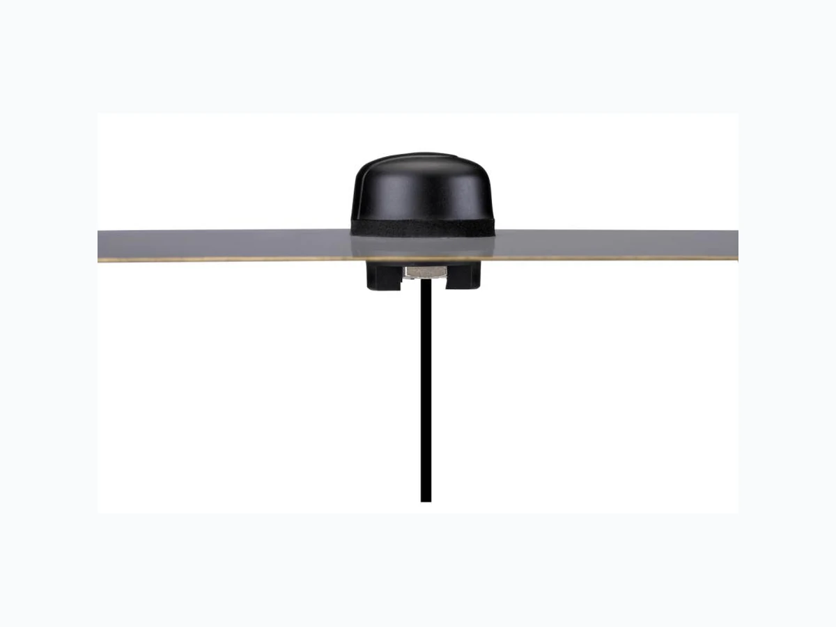
SPE-13-8-019/A/EZ Page 1 of 1 SPECIFICATION IS.05 915MHz Hercules ISM Band Antenna Part No. : IS.05.B.301111 Product Name : 915 MHz Hercules ISM Band Antenna Screw-mount (Permanent mount) Features : Low profile -Height 29mm and diameter 52mm Heavy duty screw mount UV and Vandal resistant ABS housing IP67 – Waterproof Standard cable is 3m RG174 with SMA(M)- connector fully customizable ROHS Compliant
SPE-13-8-019/A/EZ Page 2 of 2 1. INTRODUCTION The 915MHz Hercules ISM A ntenna is a high performance steel thread -mount ISM antenna for external use on vehicles and outdoor assets worldwide . Omni-directional high gain across all bands ensures constant reception and transmission. Durable UV resistant ABS housing is resistant to vandalism and direct attack. At only 29 mm h eight it complies with the latest EU height restrictions directives for roof-mounted objects, with a diameter of 52 mm. Designed to not catch on tree -branches. The antenna ca n be mounted on metal structures. 2. SPECIFICATION ELECTRICAL Standard ISM Band (MHz) 915 Frequency (MHz) 902-928 Polarization Linear Impedance 50 ohms Max Input Power 10 watts VSWR <2.5:1 *Note: The return loss, efficiency and gain in the above table, were measured on 30x30 cm metal plate with RG174 cable. For a specific case performance refers to the below plots.
SPE-13-8-019/A/EZ Page 3 of 3 MECHANICAL Dimensions Height = 29 mm and Diameter = 52 mm Cable length 3m RG174 – Fully Customable Connector SMA-Male – Fully Customable Casing UV Resistant PVC Base and Thread Nickel plated steel Thread Diameter 18 mm Weather proof gasket Rubber Sealant Rubber Stopper ENVIRONMENTAL Protection IP67 Corrosion 5% NaCl for 96hrs - Nickel plated steel base and thread Temperature Range -40°C to +85°C Thermal Shock 100 cycles -40°C to +85°C Humidity Non-condensing 65°C 95% RH Shock (Drop Test) 1m drop on concrete 6 axes Cable Pull 8 Kgf Recommended Torque Setting for Mounting 70lb/foot Maximum Torque Setting for Mounting 100lb/foot *Note: Specifications may be subject to change
Figure 1. IS.05 Antenna test set up in free space, 30x30 cm metal plate and 60x60 cm metal R&SZVL6 VNA (left) and R&S4100 CTIA 3D Chamber (Right).
4.1 Return Loss
Figure 2. Return Loss of the 915MHz Hercules ISM antenna in free space Figure 3. Return loss of the 915MHz Hercules ISM antenna on 30x30 cm metal plate.
Figure 4. Return loss of the 915Mhz Hercules ISM antenna on 60x60 cm metal plate.
4.2 Efficiency
Figure 5. Efficiency of the 915MHz Hercules ISM antenna in free space.
4.3 Gain
Figure 8. Gain of the 915MHz Hercules ISM antenna in free space. Figure 9. Gain of the 915MHz Hercules ISM antenna on 30 cm metal plate.
SPE-13-8-019/A/EZ Page 14 of 14 5. Drawings
SPE-13-8-019/A/EZ Page 15 of 15
SPE-13-8-019/A/EZ Page 16 of 16 6. INSTALLATION Recommended torque for mounting is 95Nm or 70ftlbs Maximum torque for mounting is 135.6Nm or 100ft lbs
SPE-13-8-019/A/EZ Page 17 of 17 7. PACKAGING