


 Download PDF
ILD1 VISHAY
Document overview
- PDF pages: 9
Technical content
Page 1
Optocoupler, Phototransistor Output (Dual, Quad Channel)
Features
- Current Transfer Ratio at IF = 10 mA
- Isolation Test Voltage, 5300 VRMS
- Lead-free component
- Component in accordance to RoHS 2002/95/EC and WEEE 2002/96/EC
Agency Approvals
- UL1577, File No. E52744 System Code H or J, Double Protection
- CSA 93751
- BSI IEC60950 IEC60065
- DIN EN 60747-5-2 (VDE0884) DIN EN 60747-5-5 pending Available with Option 1
- FIMKO
Description
The ILD1/ 2/ 5/ ILQ1/ 2/ 5 are optically coupled isolated pairs employing GaAs infrared LEDs and silicon NPN phototransistor. Signal information, including a DC level, can be transmitted by the drive while maintaining a high degree of electrical isolation between input and output. The ILD1/ 2/ 5/ ILQ1/ 2/ 5 are espe-
cially designed for driving medium-speed logic and can be used to eliminate troublesome ground loop and noise problems. Also these couplers can be used to replace relays and transformers in many digital interface applications such as CTR modulation. The ILD1/ 2/ 5 has two isolated channels in a single DIP package and the ILQ1/ 2/ 5 has four isolated channels per package.
Document Number 83646 Rev. 1.4, 05-Nov-04
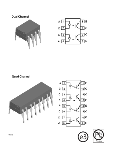
Order Information
| Part | Remarks |
|---|---|
| ILD1 | CTR > 20 %, DIP-8 |
| ILQ1 | CTR > 20 %, DIP-16 |
| ILD2 | CTR > 100 %, DIP-8 |
| ILQ2 | CTR > 100 %, DIP-16 |
| ILD5 | CTR > 50 %, DIP-8 |
| ILQ5 | CTR > 50 %, DIP-16 |
| ILD1-X007 | CTR > 20 %, SMD-8 (option 7) |
| ILD1-X009 | CTR > 20 %, SMD-8 (option 9) |
| ILD2-X006 | CTR > 100 %, DIP-8 400 mil (option 6) |
| ILD2-X007 | CTR > 100 %, SMD-8 (option 7) |
| ILD2-X009 | CTR > 100 %, SMD-8 (option 9) |
| ILD5-X009 | CTR > 50 %, SMD-8 (option 9) |
| ILQ1-X009 | CTR > 20 %, SMD-16 (option 9) |
| ILQ2-X009 | CTR > 100 %, SMD-16 (option 9) |
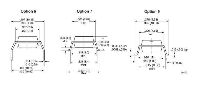
For additional information on the available options refer to Option Information.
www.vishay.com
Page 2
Absolute Maximum Ratings
Tamb = 25 °C, unless otherwise specified Stresses in excess of the absolute Maximum Ratings can cause permanent damage to the device. Functional operation of the device is not implied at these or any other conditions in excess of those given in the operational sections of this document. Exposure to absolute Maximum Rating for extended periods of the time can adversely affect reliability.
Input
| Parameter | Test condition | Symbol | Value | Unit |
|---|---|---|---|---|
| Reverse voltage | V R | 6.0 | V | |
| Forward current | I F | 60 | mA | |
| Surge current | I FSM | 2.5 | A | |
| Power dissipation | P diss | 100 | mW | |
| Derate linearly from 25 °C | 1.3 | mW/°C |
Output
| Parameter | Test condition | Part | Symbol | Value | Unit |
|---|---|---|---|---|---|
| Collector-emitter reverse voltage | ILD1 | V CER | 50 | V | |
| ILQ1 | V CER | 50 | V | ||
| ILD2 | V CER | 70 | V | ||
| ILQ2 | V CER | 70 | V | ||
| ILD5 | V CER | 70 | V | ||
| ILQ5 | V CER | 70 | V | ||
| Collector current | I C | 50 | mA | ||
| t < 1.0 ms | I C | 400 | mA | ||
| Power dissipation | P diss | 200 | mW | ||
| Derate linearly from 25 °C | 2.6 | mW/°C |
Coupler
| Parameter | Test condition | Symbol | Value | Unit |
|---|---|---|---|---|
| Isolation test voltage (between emitter and detector referred to standard climate 25 °C/ 50 % RH, DIN 50014) | V ISO | 5300 | V RMS | |
| Creepage | ≥ 7.0 | mm | ||
| Clearance | ≥ 7.0 | mm | ||
| Isolation resistance | V = 500 V, T = 25 °C IO amb | R IO | 1012 | Ω |
| V = 500 V, T = 100 °C IO amb | R IO | 1011 | Ω | |
| Package power dissipation | P tot | 250 | mW | |
| Derate linearly from 25 °C | 3.3 | mW/°C | ||
| Storage temperature | T stg | - 40 to + 150 | °C | |
| Operating temperature | T amb | - 40 to + 100 | °C | |
| Junction temperature | T j | 100 | °C | |
| Soldering temperature | 2.0 mm from case bottom | T sld | 260 | °C |
www.vishay.com
Document Number 83646 Rev. 1.4, 05-Nov-04
Page 3
Electrical Characteristics
Tamb = 25 °C, unless otherwise specified Minimum and maximum values are testing requirements. Typical values are characteristics of the device and are the result of engineering evaluation. Typical values are for information only and are not part of the testing requirements.
Input
| Parameter | Test condition | Symbol | Min | Typ. | Max | Unit |
|---|---|---|---|---|---|---|
| Forward voltage | I = 60 mA F | V F | 1.25 | 1.65 | V | |
| Reverse current | V = 6.0 V R | I R | 0.01 | 10 | µA | |
| Capacitance | V = 0 V, f = 1.0 MHz R | C O | 25 | pF | ||
| Thermal resistance, junction to lead | T thJL | 750 | K/W |
Output
| Parameter | Test condition | Symbol | Min | Typ. | Max | Unit |
|---|---|---|---|---|---|---|
| Collector-emitter capacitance | V = 5.0 V, f = 1.0 MHz CE | C CE | 6.8 | pF | ||
| Collector-emitter leakage current | V = 10 V VCE | I CEO | 5.0 | 50 | nA | |
| Saturation voltage, collector- emitter | I = 1.0 mA, I = 20 µA CE B | V CESAT | 0.25 | 0.4 | V | |
| DC forward current gain | V = 10 V, I = 20 µA CE B | HFE | 200 | 650 | 1800 | |
| DC forward current gain saturated | V = 0.4 V, I = 20 µA CE B | HFE sat | 120 | 400 | 600 | |
| Thermal resistance, junction to lead | R thjl | 500 | K/W |
Coupler
| Parameter | Test condition | Symbol | Min | Typ. | Max | Unit |
|---|---|---|---|---|---|---|
| Capacitance (input-output) | V = 0 V, f = 1.0 MHz IO | C IO | 0.8 | pF |
Current Transfer Ratio
| Parameter | Test condition | Part | Symbol | Min | Typ. | Max | Unit |
|---|---|---|---|---|---|---|---|
| Current Transfer Ratio (collector-emitter saturated) | I = 10 mA, V = 0.4 V F CE | ILD1 ILQ1 | CTR CEsat | 75 | % | ||
| ILD2 ILQ2 | CTR CEsat | 170 | % | ||||
| ILD5 ILQ5 | CTR CEsat | 100 | % | ||||
| Current Transfer Ratio (collector-emitter) | I = 10 mA, V = 10 V F CE | ILD1 ILQ1 | CTR CE | 20 | 80 | 300 | % |
| ILD2 ILQ2 | CTR CE | 100 | 200 | 500 | % | ||
| ILD5 ILQ5 | CTR CE | 50 | 130 | 400 | % |
Document Number 83646
www.vishay.com
Rev. 1.4, 05-Nov-04
Page 4
Typical Switching Times
Non-saturated Switching Timing
| Parameter | Current | Delay | Rise time | Storage | Fall time | Propagation H-L | Propagation L-H |
|---|---|---|---|---|---|---|---|
| Test condition | V = 5.0 V, R = 75 Ω, 50 % of V CE L PP | ||||||
| Symbol | I F | t D | t r | t S | t f | t PHL | t PLH |
| Unit | mA | µs | µs | µs | µs | µs | µs |
| ILD1 ILQ1 | 20 | 0.8 | 1.9 | 0.2 | 1.4 | 0.7 | 1.4 |
| ILD2 ILQ2 | 5.0 | 1.7 | 2.6 | 0.4 | 2.2 | 1.2 | 2.3 |
| ILD5 ILQ5 | 10 | 1.7 | 2.6 | 0.4 | 2.2 | 1.1 | 2.5 |
Saturated Switching Timing
| Parameter | Current | Delay | Rise time | Storage | Fall time | Propagation H-L | Propagation L-H |
|---|---|---|---|---|---|---|---|
| Test condition | V = 0.4 V, R = 1.0 kΩ, V = 5.0 V, V = 1.5 V CE L CC TH | ||||||
| Symbol | I F | t D | t r | t S | t f | t PHL | t PLH |
| Unit | mA | µs | µs | µs | µs | µs | µs |
| ILD1 ILQ1 | 20 | 0.8 | 1.2 | 7.4 | 7.6 | 1.6 | 8.6 |
| ILD2 ILQ2 | 5.0 | 1.0 | 2.0 | 5.4 | 13.5 | 5.4 | 7.4 |
| ILD5 ILQ5 | 10 | 1.7 | 7.0 | 4.6 | 20 | 2.6 | 7.2 |
Common Mode Transient Immunity
| Parameter | Test condition | Symbol | Min | Typ. | Max | Unit |
|---|---|---|---|---|---|---|
| Common mode rejection, output high | V = 50 V P-P, R = 1.0 kΩ, CM L I = 0 mA F | CM H | 5000 | V/µs | ||
| Common mode rejection, output low | V = 50 V , R = 1.0 kΩ, CM P-P L I = 10 mA F | CM L | 5000 | V/µs | ||
| Common mode coupling capacitance | C CM | 0.01 | pF |
www.vishay.com
Document Number 83646 Rev. 1.4, 05-Nov-04
Page 5
Typical Characteristics (Tamb = 25 °C unless otherwise specified)
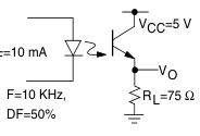
iild1_01
Figure 1. Non-saturated Switching Schematic
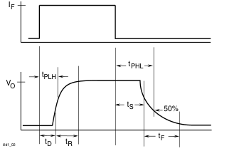
Figure 2. Non-saturated Switching Timing
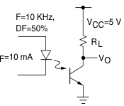
iild1_03
Figure 3. Saturated Switching Schematic
Document Number 83646 Rev. 1.4, 05-Nov-04
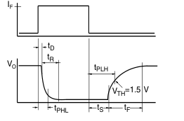
iild1_04
Figure 4. Saturated Switching Timing
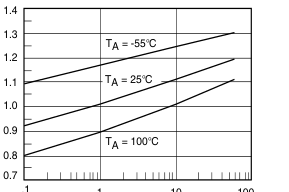
1 10 100
IF - Forward Current - mA
iild1_05
Figure 5. Normalized Non-Saturated and Saturated CTR vs. LED
Current
1.5
| Normalized t VCE = 10 V, TA= 25°C | o: IF = 10 mA | |
| CTRce(sat) | VCE = 0.4 V NCTR | |
| NCTR(SAT | ) |
1.0
0.5
0.0 .1
1 10 100
IF - LED Current - mA
iild1_06
Figure 6. Normalized Non-Saturated and Saturated CTR vs. LED
Current
www.vishay.com
Page 6
1.5
| Normalized VCE = 10 V CTRce(sat) | to: , IF = 10 mA, TA= VCE = 0.4 V | 25°Cˇ |
| TA= 50°C | NCTR | |
| NCTR(SAT) |
1.0
0.5
0.0 .1
1 10 100
IF - LED Current - mA
iild1_07
iild1_10
Figure 7. Normalized Non-Saturated and Saturated CTR vs. LED
Current
1.5
| Normalized VCE = 10 V TA= 25°C | to: , IF = 10 mA | |
| CTRce(sat) TA= 70°C | VCE = 0.4 V NCTR | |
| NCTR(SAT) |
1.0
0.5
0.0 .1 1 10 100
IF - LED Current - mA
iild1_08
iild1_11
Figure 8. Normalized Non-Saturated and Saturated CTR vs. LED
Current
1.5
| Normalized VCE = 10 CTRce(sat) | to: V, IF = 10 mA, TA VCE = 0.4 V | = 25°C |
| TA = 85°C | NCTR | |
| NCTR(SAT | ) |
1.0
0.5
0.0 .1
1 10 100
IF - LED Current - mA
iild1_09
iild1_12
Figure 9. Normalized Non-Saturated and Saturated CTR vs. LED
Current
www.vishay.com
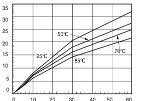
40
0 10 20 30
50 60
IF - LED Current - mA
Figure 10. Collector-Emitter Current vs. Temperature and LED
Current
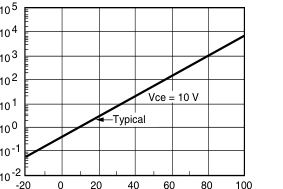
TA - Ambient Temperature - °C
Figure 11. Collector-Emitter Leakage Current vs.Temp.
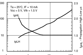
.1
1 10 100
RL - Collector Load Resistor - kΩ
Figure 12. Propagation Delay vs. Collector Load Resistor
Document Number 83646 Rev. 1.4, 05-Nov-04
Page 7
Package Dimensions in Inches (mm)
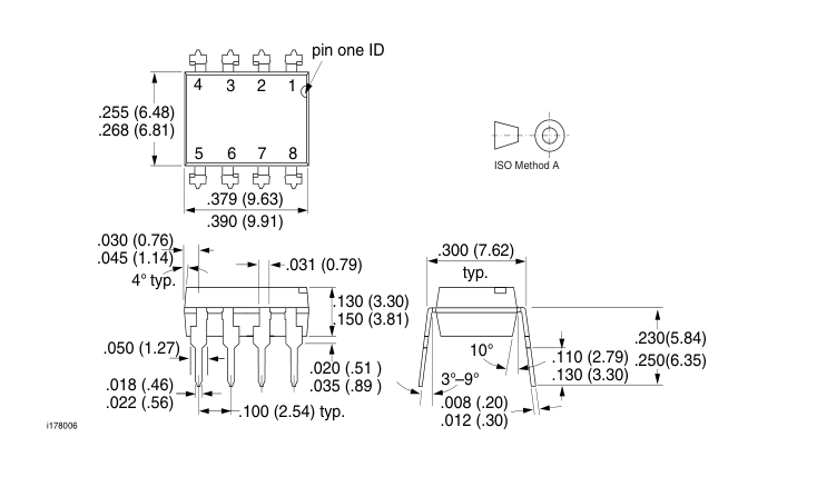
Package Dimensions in Inches (mm)
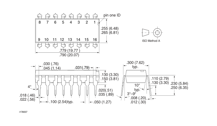
Document Number 83646
www.vishay.com
Rev. 1.4, 05-Nov-04
Page 8
www.vishay.com
Document Number 83646
Rev. 1.4, 05-Nov-04
Page 9
Ozone Depleting Substances Policy Statement
It is the policy of Vishay Semiconductor GmbH to 1. Meet all present and future national and international statutory requirements. 2. Regularly and continuously improve the performance of our products, processes, distribution and operatingsystems with respect to their impact on the health and safety of our employees and the public, as well as their impact on the environment. It is particular concern to control or eliminate releases of those substances into the atmosphere which are known as ozone depleting substances (ODSs). The Montreal Protocol (1987) and its London Amendments (1990) intend to severely restrict the use of ODSs and forbid their use within the next ten years. Various national and international initiatives are pressing for an
earlier ban on these substances. Vishay Semiconductor GmbH has been able to use its policy of continuous improvements to eliminate the use of ODSs listed in the following documents. 1. Annex A, B and list of transitional substances of the Montreal Protocol and the London Amendments respectively 2. Class I and II ozone depleting substances in the Clean Air Act Amendments of 1990 by the Environmental Protection Agency (EPA) in the USA 3. Council Decision 88/540/EEC and 91/690/EEC Annex A, B and C (transitional substances) respectively. Vishay Semiconductor GmbH can certify that our semiconductors are not manufactured with ozone depleting substances and do not contain such substances.
We reserve the right to make changes to improve technical design
and may do so without further notice.
Parameters can vary in different applications. All operating parameters must be validated for each customer application by the customer. Should the buyer use Vishay Semiconductors products for any unintended or unauthorized application, the buyer shall indemnify Vishay Semiconductors against all claims, costs, damages, and expenses, arising out of, directly or indirectly, any claim of personal damage, injury or death associated with such unintended or unauthorized use.
Vishay Semiconductor GmbH, P.O.B. 3535, D-74025 Heilbronn, Germany Telephone: 49 (0)7131 67 2831, Fax number: 49 (0)7131 67 2423
Document Number 83646
www.vishay.com
Rev. 1.4, 05-Nov-04