


 Download PDF
H5009-5012 INTERSIL
Document overview
- PDF pages: 3
Technical content
Page 1
IH5009-5012, 5014, 5016-5020, 5022, 5024
May 1999
Features
- Switches Analog Signals Up to 20 Volts Peak-to-Peak
- Each Channel Complete - Interfaces with Most Integrated Logic
- Switching Speeds Less Than 0.5µs
- ID(OFF) Less Than 500pA Typical at 70oC
- Effective rDS(ON) - 5Ω to 50Ω
- Commercial and Military Temperature Range Operation
Part Number Information
| PART NUMBER | CHANNELS | LOGIC LEVEL | PACKAGE | PKG NO. |
|---|---|---|---|---|
| IH5009 | 4 | +15 | DD, PD | |
| IH5010 | 4 | +5 | DD, PD | |
| IH5011 | 4 | +15 | DE, PE | |
| IH5012 | 4 | +5 | DE, PE | |
| IH5014 | 3 | +5 | DD, PD | |
| IH5016 | 3 | +5 | DE, PE | |
| IH5017 | 2 | +15 | PA | |
| IH5018 | 2 | +5 | DD, PA | |
| IH5019 | 2 | +15 | DE, PA | |
| IH5020 | 2 | +5 | DE, PA | |
| IH5022 | 1 | +5 | DD, PA | |
| IH5024 | 1 | +5 | PA |
NOTE: Mil-Temperature range (-55oC to 125oC) available in ceramic packages only.
Virtual Ground Analog Switch
Description
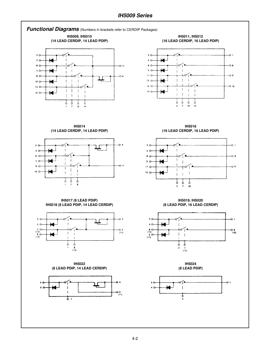
The IH5009 series of analog switches were designed to fill the need for an easy-to-use, inexpensive switch for both industrial and military applications. Although low cost is a primary design objective, performance and versatility have not been sacrificed. Each package contains up to four channels of analog gating and is designed to eliminate the need for an external driver. The odd numbered devices are designed to be driven directly from TTL open collector logic (15 volts) while the even numbered devices are driven directly from low level TTL logic (5 volts). Each channel simulates a SPDT switch. SPST switch action is obtained by leaving the diode cathode
unconnected; for SPDT action, the cathode should be grounded (0V). The parts are intended for high performance multiplexing and commutating usage. A logic “0” turns the channel ON and a logic “1” turns the channel OFF.
IH50XX
M DE
PACKAGE
PA - 8 LEAD PDIP PD - 14 LEAD PDIP PE - 16 LEAD PDIP DD - 14 LEAD CERDIP DE - 16 LEAD CERDIP
TEMPERATURE RANGE
M = MILITARY (-55oC to 125oC) C = COMMERCIAL (0oC to 70oC)
BASIC PART NUMBER
CAUTION: These devices are sensitive to electrostatic discharge. Users should follow proper IC Handling Procedures.
File Number 3129.1
Copyright © Harris Corporation 1999
4-1
Page 2
Page 3
IH5009 Series
Absolute Maximum Ratings
Positive Analog Signal Voltage . . . . . . . . . . . . . . . . . . . . . . . . . . 30V Negative Analog Signal Voltage . . . . . . . . . . . . . . . . . . . . . . . . .-15V Diode Current . . . . . . . . . . . . . . . . . . . . . . . . . . . . . . . . . . . . . .10mA Power Dissipation (Note) . . . . . . . . . . . . . . . . . . . . . . . . . . . 500mW
Operating Conditions
Temperature Range 5009C Series . . . . . . . . . . . . . . . . . . . . . . . . . . . . . . .0oC to 70oC 5009M Series . . . . . . . . . . . . . . . . . . . . . . . . . . . . -55oC to 125oC
Thermal Information
Maximum Storage Temperature Range . . . . . . . . . .-65oC to 150oC Maximum Lead Temperature (Soldering 10s) . . . . . . . . . . . . . 300oC
CAUTION: Stresses above those listed in “Absolute Maximum Ratings” may cause permanent damage to the device. This is a stress only rating and operation of the device at these or any other conditions above those indicated in the operational sections of this specification is not implied.
NOTE: Dissipation rating assumes device is mounted with all leads welded or soldered to printed circuit board in ambient temperature below 75oC. For higher temperature, derate at rate of 5m/WoC.
Electrical Specifications
(Per Channel)
| PARAMETER | (NOTE 1) SYMBOL | (NOTE 4) TEST CONDITIONS | (NOTE 2) TYPE | -55oC (M) 0oC (C) MIN/MAX | 25oC | 125oC(M) 70oC (C) MIN/MAX | UNITS | |
|---|---|---|---|---|---|---|---|---|
| TYP | MIN/MAX | |||||||
| Input Current-ON | IIN(ON) | ALL | VIN = 0V, ID = 2mA | - | 0.01 | ±0.5 | 100 | µA |
| Input Current-OFF | IIN(OFF) | 5V Logic Ckts | VIN = +4.5V, VA = ±10V | - | 0.04 | ±0.5 | 20 | nA |
| Input Current-OFF | IIN(OFF) | 15V Logic Ckts | VIN = +11V, VA = ±10V | - | 0.04 | ±0.5 | 20 | nA |
| Channel Control Voltage-ON | VIN(ON) | 5V Logic Ckts | Note 3 | 0.5 | - | 0.5 | 0.5 | V |
| Channel Control Voltage-ON | VIN(ON) | 15V Logic Ckts | Note 3 | 1.5 | - | 1.5 | 1.5 | V |
| Channel Control Voltage-OFF | VIN(OFF) | 5V Logic Ckts | Note 3 | - | - | 4.5 | 4.5 | V |
| Channel Control Voltage-OFF | VIN(OFF) | 15V Logic Ckts | Note 3 | - | - | 11.0 | 11.0 | V |
| Leakage Current-OFF | ID(OFF) | 5V Logic Ckts | VIN = +4.5V, VA = ±10V | - | 0.02 | ±0.5 | 20 | nA |
| Leakage Current-OFF | ID(OFF) | 15V Logic Ckts | VIN = +11V, VA = ±10V | - | 0.02 | ±0.5 | 20 | nA |
| Leakage Current-ON | ID(ON) | 5V Logic Ckts | VIN = 0V, IS = 1mA | - | 0.30 | ±1.0 | 1000 (M) 200 (C) | nA |
| Leakage Current-ON | ID(ON) | 15V Logic Ckts | VIN = 0V, IS = 1mA | - | 0.10 | ±0.5 | 500 (M) 100 (C) | nA |
| Leakage Current-ON | ID(ON) | 5V Logic Ckts | VIN = 0V, IS = 2mA | - | - | 1.0 | 10 | µA |
| Leakage Current-ON | ID(ON) | 15V Logic Ckts | VIN = 0V, IS = 2mA | - | - | 2.0 | 100 | µA |
| Drain-Source ON-Resistance | rDS(ON) | 5V Logic Ckts | ID = 2mA, VIN = 0.5V | 150 | 90 | 150 | 385 (M) 240 (C) | Ω |
| Drain-Source ON-Resistance | rDS(ON) | 15V Logic Ckts | ID = 2mA, VIN = 1.5V | 100 | 80 | 100 | 250 (M) 160 (C) | Ω |
| Turn-ON Time | t(ON) | All | - | 150 | 500 | - | ns | |
| Turn-OFF Time | t(OFF) | All | - | 300 | 500 | - | ns | |
| Cross Talk | CT | All | f = 100Hz | - | 120 | - | - | dB |
NOTES: 1. (OFF) and (ON) subscript notation refers to the conduction state of the FET switch for the given test. 2. Refer to Figure 1 for definition of terms. 3. VIN(ON) and VIN(OFF) are test conditions guaranteed by the tests of rDS(ON) and ID(OFF) respectively. 4. “5V Logic CKTS” applies to even-numbered devices. “15V Logic CKTS” applies to odd-numbered devices.
4-3