

 Download PDF
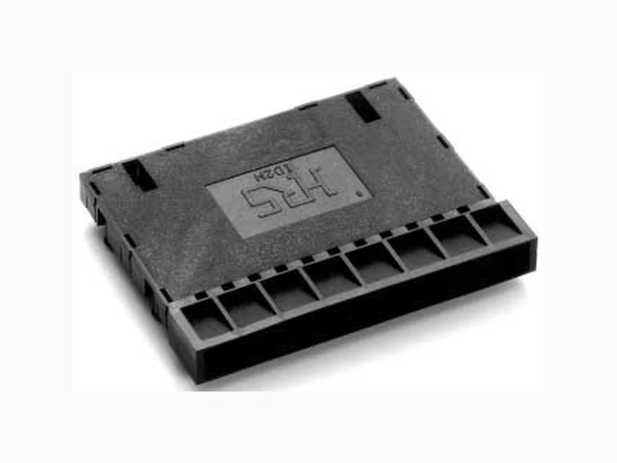
ID2M-8S-2.54DS HIROSE
Document overview
- PDF pages: 4
Technical content
Page 1

IFeatures
1. Suited to Smart Cards Conforming to
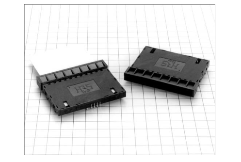
ISO-7816 Smart cards feature a high level of reliability in terms of security when compared to contemporary credit cards and so these cards will be indispensable in the anticipated systems of the future such as settlement of accounts.The rapid worldwide growth seen in digital satellite broadcasting also makes use of these smart cards, which are used in the associated fee payment system. The ID2M Series of smart card sokets were developed for use with these digital satellite broadcast receiver (IRD) and are considered to be userfriendly. These smart card sockets can be used in a wide range of applications.
2. Eight Contacts
Sockets are available with 8 contacts only, in conformity with ISO-7816
3. Equipped with a Card Detection Switch
A switch that detects whether the smart card has been inserted securely prevents erroneous operation. This swich will be set to OFF(i.e., the nonconducting condition) when the smart card has been inserted all the way.
IApplications
Digital satellite broadcast receivers (IRD) and other devices that use smart cards.
4. Excellent Detection Switch Construction
- The distance from the dip post to the contact has been extended to form a contact shape that is not susceptible to tje adherence of flux.
- A 2-point contact structure using two springs improves contact reliabilty.
- The smart card holding structure keeps cards in place and prevents erroneous operation of the detecion swich due to light shocks and vibration.Taking into account inadvertent card removal,the design also features a spring-shaped portion on top of the housing that holds the card.
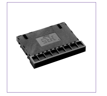
5. Large Insertion Slot
The insertion slot for the smart card has been made large to improve ease of use.
6. Equipped with a Board Provisional
This socket has s fastening boss for 1.6mm thich boards, a design feature that keeps boards in place at time of mounting.
7. Insertion/Removal Guarantee
of 10,000 Times
C35
Page 2
IProduct Specification
| Rating | Current rating 1A Voltage rating 150V AC | Operating temperature -50ç to +80ç(NOTE 1) Operating humidity 40 to 80% | Storage temperature -40ç to +60ç(NOTE 1) Storage humidity 40 to 70%(NOTE 2) | ||
| Item | Specification | Conditions | |||
| 1. Insulation resistance | 1000 M ohms min. | 500 VDC | |||
| 2. Withstanding voltage | No flashover or insulation breakdown. | 500 V AC / 1 minute | |||
| 3. Contact resistance | 30 m ohms max.(40m ohms max.for switch portion) | 20 mV AC max.,measured at 1 mA | |||
| 4. Vibration | No electrical discontinuity of 1µs or more | Frequency: 10 to 55 Hz, single amplitude of 0.75 mm , 2 hours in each of the 3 directions. | |||
| 5. Humidity(Steady state) | Contact resistance: 40 m ohms max. (50 m ohms max.for the switch portion) Insulation resistance: 1000M ohms man. | 96 hours at temperature of 40ç and humidity of 90% to 95% | |||
| 6. Temperature cycle | Contact resistance: 40 m ohms max. (50 m ohms max.for the switch portion) Insulation resistance: 1000M ohms man. | (-55ç: 30 minutes/ 5 to 35ç:10 minutes/85ç:30 minutes / 5 to 35ç:10 minutes)for 5 cycles | |||
| 7.Durability (mating/unmating) | Contact resistance: 40 m ohms max. (50 m ohms max.for the switch portion) | 100000 cycles | |||
| 9.Resistance to soldering heat | No deformation of components affecting performance. | Flow: 255° for 5 seconds Manual soldering: 300ç for 3 seconds | |||
Note 1: Includes temperature rise caused by current flow. Note 2: The term "storage" refers to products stored for long period of time prior to mounting and use. Operating Temperature Range and Humidity range covers non- conducting condition of installed connectors in storage, shipment or during transportation.
Materials
| Part | Material | Finish | Remarks |
|---|---|---|---|
| Insulator | PBT | Color:Black | UL94V-0 |
| Singnal contacts | Phosphor bronze | Contact portion:gold plating Lead portion: Solder plating | |
| Switch contacts | Phosphor bronze | Gold plating | |
| Brass | Gold plating | ||
| Ordering Information ID2M -- 8 S -- 2.54 DS 1 2 3 4 5 1 Series name: ID2M 2 Number of contacts:8 3 Contacts type S: Socket 4 Contact pitch: 2.54 mm Terminal type 5 DS:Right-angle dip | |||
C36
Page 3
Socket
62.4

| 62 A M2DI 51.2 51 11 A 64 61 54.2 (12.5) 6.9 8.2 4.8 (0.3) (0.8) 3.2 (3.81) 20 (2.54) 30 (22.1) (7.62) (2.54) 58 (38.1) (0.95) Smart card A-A (7.62) (4.8) (39.5) (46) (Card insertion depth) | |||
| Part Number | CL N | o. Number of Contacts | Packaging |
| ID2M-8S-2.54DS | 645-015 | 1-6 8 | Tray |
| nttiinngg ppaatttteerrnn 58±0.05 33.53±0.05 22.1±0.05 7.62±0.05 381±0.05 9.05±0.05 2.54±0.05 40.5±0.05 5±0.05 2.54±0.05 10-Ø1+0.1 +0 15±0.05 38.1±0.05 20±0.05 30±0.05 4-Ø3.2±0.05 2-Ø1.9 + +0 0.1 | |||
PCB mounting pattern
Insertion Slot Side
C37
Page 4
Method of Using the Sockets
- The orientation of the card should have the contact surface inserted face-down as illustrated in the diagram below.
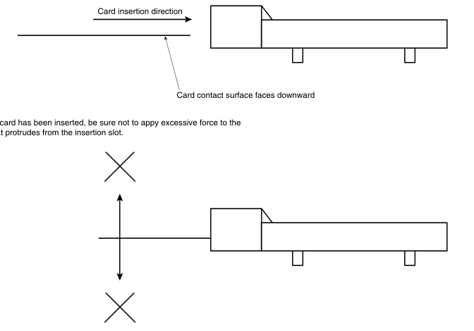
card portion that protrudes from the insertion slot.
- When the board warps greatly due to solder flow, the socket may rise up from the board.Please limit as much as possible this board warpage due to solder flow.
Washing Conditions
This product is a no-wash item, but in the case of washing, please observe the following conditions.
1.Oranic Solvent Washing
| Solvent | Normal temperature washing | Heated washing |
| IPA(Isopropyl alcohol) | Yes | Yes |
| HCFC(Hydrochlorofluorocarbon) | Yes | Yes |
2.Water Type Washing
When using water type cleaning agents(e.g., terpene, and alkali saponifiers), select the cleaning agent based on the documentation issued by the various manufacturers of cleaning agents which describes the effects on metals and resins.Be careful that parts are not left with moisture remaining on them
3.Washing Precautions
Residual flux or cleaning agent on the contacts when washing with organic solvents or water type cleaners can give rise to the deterioration of electrical performance. In this regard it is important to check whether a thorough washing has been performed.
C38