
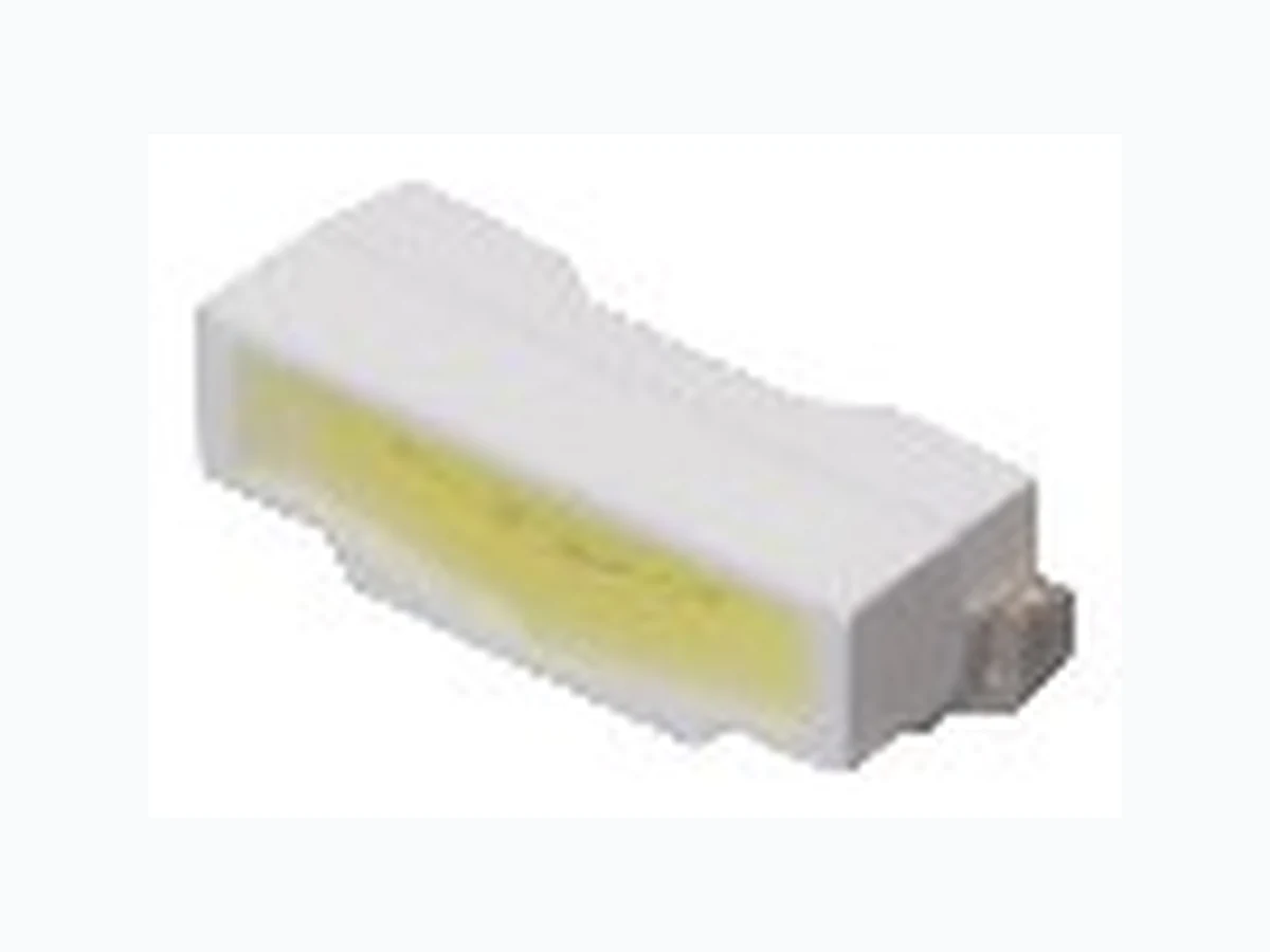
HSW112LTM STANLEY
Document overview
- Manufacturer or author: Provided By www.digicamel.com(FREE DATASHEET DOWNLOAD SITE)
- PDF pages: 16
Technical content
Features
Cellular Phone, Mobile Equipment, Electric Household Appliances, Other General Applications Page 1 ・Outer Dimension 2.8 x 0.95 x 0.8mm ( L x W x H ) ・Temperature range Storage Temperature : -40℃~100℃ Operating Temperature : -30℃~85℃ ・Lead–free soldering compatible ・RoHS compliant Package Product features Chromaticity coordinates Spatial distribution Die materials Rank grouping parameter Assembly method Soldering methods Taping and reel ESD Sorted by luminous intensity and chromaticity per rank taping Auto pick & place machine (Auto Mounter) 3,000pcs per reel in a 8mm width tape. (Standard) Reel diameter:φ180mm 1kV (HBM) 115 deg. Right Angle Type, 1142LTM : Diffused pale yellow resin, 1152LTM : Diffused pale orange resin HSW11□2LTM Series x = 0.299YP., y = 0.296TYP. (Condition : IF=20mA) InGaN Right Angle Type White LED 2008.12.22 Recommendation of Reflow soldering / Flow Soldering (Dip Soldering) is impossible.
Color and Luminous Intensity Page 2 MIN . TYP. I F TYP. I F HSW1142LTM InGaN White Pale Yellow 1,720 2,000 20 5.0 20 HSW1152LTM※1 InGaN White Pale Orange 1,200 1,440 20 3.6 20 Part No. Material Emitted Color Luminous Flux Iv (mcd) φ v (lm) Lens Color Luminous Intensity HSW11□2LTM Series Right Angle Type White LED ※1 High Color reproduction Type ※Note : The above luminous intensity(Iv) is the setup values of the sorting machine. (Tolerance : IV… ±10%) (Ta=25℃) 2008.12.22
Power Dissipation P d 114 114 mW Forward Current I F 30 30 mA Pulse Forward Current ※1 IFRM 100 100 mA ⊿IF 0.4 0.4 mA/ ℃ ⊿IFRM 1.33 1.33 mA/ ℃ Revers e Voltage V R 55 V Operating Temperature Topr ℃ Storage Temperature Tstg ℃ Item Symbol Unit Derating (Ta=25℃ or higher) Absolute Maximum Ratings -30~+85 -40~+100 HSW11□2LTM Series Right Angle Type White LED ※1 IFRM Measurement condition : Pulse Width≦1ms, Duty≦1/20 (Ta=25℃) 2008.12.22
Electro-Optical Characteristics Condition 1142LTM 1152LTM TYP. 3.2 3.2 MAX. 3.5 3.5 Reverse Current V R=5V I R MAX. 50 50 μA Half Intensity Angle IF=20mA 2 θ1/2 TYP. 115 115 deg. x TYP. 0.299 0.299 - y TYP. 0.296 0.296 - UnitItem Symbol VF V Characteris tics Chromaticity Coordinates IF=20mA Forward Voltage ※1 IF=20mA Page 4 HSW11□2LTM Series Right Angle Type White LED (Ta=25℃) 2008.12.22 ※1 Forward Voltage Tolerance Range : ±0.1V
Luminous Intensity Rank (1142LTM) Page 5 Rank IV(mcd) MIN. MA X. VC 1,720 1,860 VD 1,860 2,000 WA 2,000 2,200 WB 2,200 2,400 Condition IF=20mA Intensity Tolerance each Rank : +/-10% HSW11□2LTM Series Right Angle Type White LED ˞Please contact our sales staff concerning rank designation. 2008.12.22 (Ta=25℃) Luminous Intensity Rank (1152LTM) (Ta=25℃) Rank IV(mcd) MIN. MA X. UC 1,200 1,300 UD 1,300 1,440 VA 1,440 1,580 VB 1,580 1,720 VC 1,720 1,860 Condition I F=20mA Intensity Tolerance each Rank : +/-10% ˞Please contact our sales staff concerning rank designation.
Sorting Chart for Chromaticity Coordinates Page 6 R a n k xyxyxyxy LEFT DOWN point LEFT UP point RI GHT UP point RI GHT UP point HSW11□2LTM Series Right Angle Type White LED 2008.12.22 (Ta=25℃) Chromaticity Coordinates Tolerance Each Rank : +/-0.01 ˞ Please contact our sales staff concerning rank designation.
Forward Current vs. Relative Intensity Condition : Ta = 25℃ Forward Current IF(mA) Forward Voltage vs. Forward Current Condition : Ta = 25℃ Forward Voltage VF(V) Spectral Distribution Relative Intensity vs. Wavelength Condition : Ta = 25℃, IF = 20mA Wavelength [nm] Technical Data (1142LTM) Page 7 2008.12.22 Spatial Distribution Example Condition : Ta = 25℃ Forward Current IF(mA) Relative Intensity Relative Intensity HSW11□2LTM Series Right Angle Type White LED
Ambient Temperature vs. Relative Intensity Condition : IF = 20mA Ambient Temperature : Ta(℃) Derating Ambient Temperature vs. Maximum Forward Current Ambient Temperature : Ta(℃) Page 8 2008.12.22 Maximum Forward Current : IF MAX. (mA) Relative Intensity Ambient Temperature vs. Forward Voltage Condition : IF = 20mA Ambient Temperature : Ta(℃) Forward Voltage VF(V) Forward Current vs. Chromaticity Condition : Ta = 25℃ x y HSW11□2LTM Series Right Angle Type White LED Technical Data (1142LTM)
2008.12.22 Ambient Temperature vs. Chromaticity Condition : IF = 20mA x y HSW11□2LTM Series Right Angle Type White LED Technical Data (1142LTM)
Forward Current vs. Relative Intensity Condition : Ta = 25℃ Forward Current IF(mA) Forward Voltage vs. Forward Current Condition : Ta = 25℃ Forward Voltage VF(V) Spectral Distribution Relative Intensity vs. Wavelength Condition : Ta = 25℃, IF = 20mA Wavelength [nm] Technical Data (1152LTM) Page 10 2008.12.22 Spatial Distribution Example Condition : Ta = 25℃ Forward Current IF(mA) Relative Intensity Relative Intensity HSW11□2LTM Series Right Angle Type White LED
Ambient Temperature vs. Relative Intensity Condition : IF = 20mA Ambient Temperature : Ta(℃) Derating Ambient Temperature vs. Maximum Forward Current Ambient Temperature : Ta(℃) Page 11 2008.12.22 Maximum Forward Current : IF MAX. (mA) Relative Intensity Ambient Temperature vs. Forward Voltage Condition : IF = 20mA Ambient Temperature : Ta(℃) Forward Voltage VF(V) Forward Current vs. Chromaticity Condition : Ta = 25℃ x y HSW11□2LTM Series Right Angle Type White LED Technical Data (1152LTM)
2008.12.22 Ambient Temperature vs. Chromaticity Condition : IF = 20mA x y HSW11□2LTM Series Right Angle Type White LED Technical Data (1152LTM)
Recommended Soldering Pattern Page 13 (Unit: mm) (Unit: mm) Taping Specification (Unit: mm) ・Quantity: 3,000pcs/ reel (standard) HSW11□2LTM Series Right Angle Type White LED 2008.12.22 Weight: (5.3)mg
HSW11□2LTM Series Right Angle Type White LED 2008.12.22 Reflow Soldering Conditions 1) The above profile temperature gives the maximum temperature of the LED resin surface. Please set the temperature so as to avoid exceeding this range. 2) Total times of reflow soldering process shall be no more than 2 times. When the second reflow soldering process is performed, intervals between the first and second reflow should be short as possible (while allowing some time for the component to return to normal temperature after the first reflow) in order to prevent the LED from absorbing moisture. Manual Soldering Conditions Iron tip temp. Soldering time and frequency 3 s 1 time 350 ℃ (MAX.) (MAX.) (MAX.)
Reliability Testing Result Page 15 R eliability T esting R esult Applicable S tandard T esting Conditions Duration F ailure R oom T emp. Operating Life EI A J ED - 4701/100(101) Ta = 2 5℃, IF = 30mA 1,000 h 0/20 High Temp. Operating Life EI A J ED - 4701/100(101) Ta = 8 5℃ ,IF = 6mA 1,000 h 0/20 Low Temp. Operating Life EI A J ED - 4701/100(101) Ta = -3 0℃, IF = 20mA 1,000 h 0/20 Wet High Temp. Operating Life EI A J ED - 4701/100(102) Ta = 6 0℃, 90%, IF = 16mA 1,000 h 0/20 Wet High Temp. Storage Life EI A J ED - 4701/100(103) Ta = 6 0℃, 90% 1,000 h 0/20 Thermal Shock EI A J ED - 4701/100(105) Ta = -4 0℃ ~ 100℃ (each 15min.) 200 cycles 0/20 High Temp. Storage Life EI A J ED - 4701/200(201) T a = 100℃ 1,000 h 0/20 Low Temp. Storage Life EI A J ED - 4701/200(202) Ta = -4 0℃ 1,000 h 0/20 Cycled Temp. Humidity Life EI A J ED - 4701/200(203) Ta = -1 0℃ ~ 65℃, 95%, 24h/ cycle 10 cycles 0/ 20 Resistance to R eflow S oldering EI A J ED - 4701/300(301) Preheat : 150 ~ 180℃(120s Max.) Soldering Temp. : 260℃(5s) Moisture S oak : 30℃, 70%, 72h Tw i ce 0 / 2 0 Electric Static Discharge ( ESD ) EI A J ED - 4701/300(304) C = 100pF , R 2 = 1.5KΩ, ±1,000V once each polarity 0/ 20 Vibration, Variable Frequency EI A J ED - 4701/400(403) 98.1m/s (10G), 100 ~ 2KHz, 20min, XYZ each direction 2 h 0/20 Failure Criteria Items Symbols Conditions Failure criteria Luminous Intensity Iv I F=20mA Testing M in. Value < S pec. Min. Value x 0.7 Forward Voltage V F IF=20mA Testing M ax. Value ≧ Spec. M ax. Value x 1.2 Reverse Current I R VR=5V Testing M ax. Value ≧ Spec. M ax. Value x 2.5 Cosmetic Appearance - - Occurrence of notable decoloration, deformation and cracking HSW11□2LTM Series Right Angle Type White LED 2008.12.22
Special Notice to Customers Using the Products and Technical Information Shown in This Data Sheet Page 16 HSW11□2LTM Series Right Angle Type White LED 2008.12.22 1) The technical information shown in the data sheets are limited to the typical characteristics and circuit examples of the referenced products. It does not constitute the warranting of industrial property nor the granting of any license. 2) For the purpose of product improvement, the specifications, characteristics and technical data described in the data sheets are subject to change without prior notice. Therefore it is recommended that the most updated specifications be used in your design. 3) When using the products described in the data sheets, please adhere to the maximum ratings for operating voltage, heat dissipation characteristics, and other precautions for use. We are not responsible for any damage which may occur if these specifications are exceeded. 4) The products that have been described to this catalog are manufactured so that they will be used for the electrical instrument of the benchmark (OA equipment, telecommunications equipment, AV machine, home appliance and measuring instrument). The application of aircrafts, space borne application, transportation equipment, medical equipment and nuclear power control equipment, etc. needs a high reliability and safety, and the breakdown and the wrong operation might influence the life or the human body. Please consult us beforehand if you plan to use our product for the usages of aircrafts, space borne application, transportation equipment, medical equipment and nuclear power control equipment, etc. except OA equipment, telecommunications equipment, AV machine, home appliance and measuring instrument. 5) In order to export the products or technologies described in this data sheet which are under the “Foreign Exchange and Foreign Trade Control Law,” it is necessary to first obtain an export permit from the Japanese government. 6) No part of this data sheet may be reprinted or reproduced without prior written permission from Stanley Electric Co., Ltd. 7) The most updated edition of this data sheet can be obtained from the address below: http://www.stanley-components.com