


 Download PDF
HRWA10W-10R-J-HS RFE
Document overview
- PDF pages: 2
Technical content
Page 1
HIGH POWER WIRE WOUND RESISTOR HRW Series: Non-Flammable, Wire Wound
FEATURES
- Non-Flammable
- Wire Wound
PART NUMBER EXAMPLE
HRW A 10W-10R-J-HS
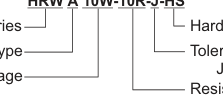
Series
Hardware
Type
Tolerance J=5%
Wattage
Resistance
SPECIFICATIONS
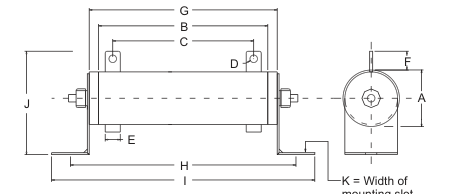
mounting slot (Models with brackets only)
A type : Fixed Resistor B type : Fixed with a tap C type : Adjustable Resistor N type : Non-inductively wound
Hardware:HS = Screw
H P = Press in Bracket HX = Special Omit = No Hardware
| Watts Power Rating | Dimensions (m/m) | Ohms Resistance Range | ||||||||||
| A±1 | B±2 | C±2 | D±0.1 | E±0.2 | F±1 | G±2 | H±2 | I±2 | J±2 | K±0.1 | ||
| 10W | 12.5 | 45 | 35 | 2.1 | 4 | 10 | 55 | 56 | 57 | 30 | 4 | 1 ~ 10K |
| 12W | 12.5 | 45 | 35 | 2.1 | 4 | 10 | 55 | 56 | 57 | 30 | 4 | 1 ~ 15K |
| 20W | 16.5 | 60 | 45 | 3 | 5 | 12 | 70 | 84 | 100 | 37 | 4 | 1 ~ 20K |
| 30W | 16.5 | 80 | 65 | 3 | 5 | 12 | 90 | 104 | 120 | 37 | 4 | 1 ~ 30K |
| 40W | 16.5 | 110 | 95 | 3 | 5 | 12 | 120 | 134 | 150 | 37 | 4 | 1 ~ 40K |
| 50W | 25 | 110 | 92 | 5.2 | 8 | 19 | 120 | 142 | 164 | 58 | 6 | 0.1 ~ 50K |
| 60W | 28 | 90 | 72 | 5.2 | 8 | 17 | 101 | 123 | 145 | 60 | 6 | 0.1 ~ 60K |
| 80W | 28 | 110 | 92 | 5.2 | 8 | 17 | 121 | 143 | 165 | 60 | 6 | 0.1 ~ 80K |
| 100W | 28 | 140 | 122 | 5.2 | 8 | 17 | 151 | 173 | 195 | 60 | 6 | 0.1 ~ 100K |
| 120W | 28 | 160 | 142 | 5.2 | 8 | 17 | 171 | 193 | 215 | 60 | 6 | 0.1 ~ 120K |
| 150W | 28 | 195 | 177 | 5.2 | 8 | 17 | 206 | 229 | 250 | 60 | 6 | 0.1 ~ 150K |
| 160W | 35 | 185 | 167 | 5.2 | 8 | 17 | 197 | 217 | 245 | 75 | 8 | 0.1 ~ 160K |
| 200W | 35 | 210 | 192 | 5.2 | 8 | 17 | 222 | 242 | 270 | 75 | 8 | 0.1 ~ 200K |
| 250W | 40 | 210 | 188 | 5.2 | 10 | 18 | 222 | 242 | 270 | 77 | 8 | 0.5 ~ 250K |
| 300W | 40 | 260 | 238 | 5.2 | 10 | 18 | 272 | 292 | 320 | 77 | 8 | 0.5 ~ 300K |
| 400W | 40 | 330 | 308 | 5.2 | 10 | 18 | 342 | 380 | 390 | 77 | 8 | 0.5 ~ 400K |
| 500W | 50 | 330 | 304 | 6.2 | 12 | 28 | 346 | 367 | 399 | 105 | 9 | 0.5 ~ 500K |
| 600W | 50 | 400 | 384 | 6.2 | 12 | 28 | 416 | 437 | 469 | 105 | 9 | 1 ~ 600K |
| 800W | 60 | 460 | 425 | 6.2 | 15 | 30 | 480 | 504 | 533 | 112 | 10 | 1 ~ 800K |
| 1000W | 60 | 540 | 505 | 6.2 | 15 | 30 | 560 | 584 | 613 | 112 | 10 | 1 ~ 1M |
| 1300W | 65 | 650 | 620 | 6.2 | 15 | 30 | 667 | 700 | 715 | 115 | 10 | 1 ~ 1.3M |
C2E01
RFE International • Tel:(949) 833-1988 • Fax:(949) 833-1788 • E-Mail Sales@rfeinc.com
REV 2002.08.14
Page 2
HIGH POWER WIRE WOUND RESISTOR HRW Series: Non-Flammable
ELECTRICAL SPECIFICATION
| Characteristics | Limits | Test methods |
| Resistance and tolerance | Resistance Nominal Resistance Tolerance 1 <R ±5%(J) 1 >R ±10%(K) | JIS-C-5202 5-1 |
| Temperature coefficient | ±200PPM/°C max | JIS-C-5202 5-2b |
| Power rating load | R/R < ±(2% + 0.05 ) (Temperature) 350°C max. | JIS-C-5202 5-4 |
| Short-time overload | 1000% rated power 5 seconds R/R < ±(2% + 0.05 ) | JIS-C-5202 5-5 |
| Insulation resistance | DC500V 100M min. | JIS-C-5202 5-6 |
| Dielectric withstanding voltage | AC3000V 1 minute | JIS-C-5202 5-7 |
ELECTRICAL CURVES
Power Derating Curve
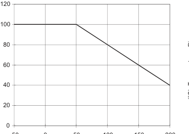
-50 0 50 100 150 200
(°C) Ambient Temperature
SHORT-TIME OVERLOAD RATING
Temperature Rise
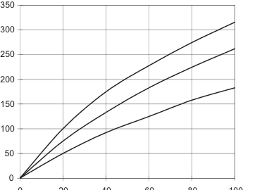
0 20 40 60 80 100
(%) Percent Rated Load
| (Second) Load Time | 1 | 2 | 3 | 4 | 5 | 10 | 30 | 60 | 180 | 300 | 600 | 900 |
| (%) Power Increase | 2600 | 2000 | 1600 | 1400 | 1300 | 1000 | 600 | 450 | 200 | 150 | 120 | 110 |
BODY TYPE CONFIGURATIONS (All Diagrams showing HS type hardware)
Type A (Fixed Resistor)
Type B (Fixed With Tap)
Type C (Adjustable Resistor)
C2E01 REV 2002.08.14