
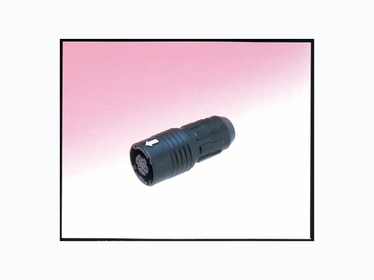

 Download PDF
HR30 HIROSE
Document overview
- PDF pages: 16
Technical content
Page 1
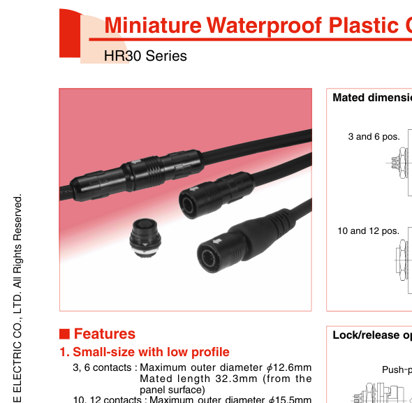
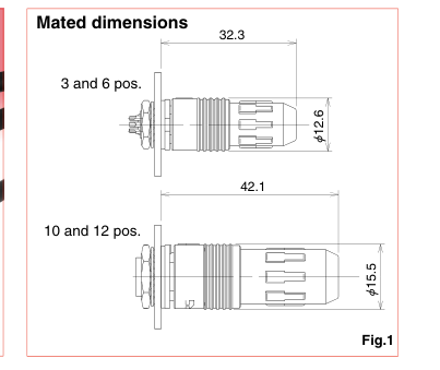
panel surface)
These small, compact connectors offer unique features available only from Hirose.
2. Waterproof construction
IP67 and 68 waterproof construction in the mated state IP67 : Left submerged in water at a depth of 1m for 30 minutes IP68 : Left submerged in water at a depth of 2m for 14 days
3. Push/pull lock
Waterproof connectors feature an easy to operate push/pull locks developed with our exclusive technology.
4. Light weight
3 and 6 contacts: 6g (plug + receptacle) 10 and 12 contacts: 9g (plug + receptacle)
5. Clamp structure
Our proprietary clamping method allows clamping the cable by simply tightening the cord ring.
6. Easy mating operation
The plug can be securely locked while holding it in your hand while mating. (Fig.2)
7. Mis-insertion prevention
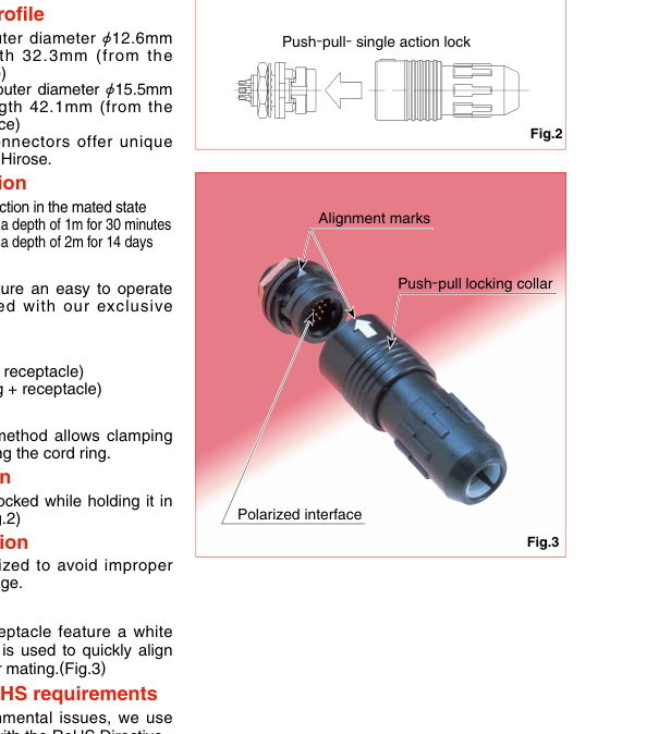
Mating portions are polarized to avoid improper mating and connector damage.
8. Mating mark
Both the plug and the receptacle feature a white index mark on them which is used to quickly align the two interfaces for proper mating.(Fig.3)
9. Complies with the RoHS requirements
In consideration of environmental issues, we use only materials that comply with the RoHS Directive.
In cases where the application will demand a high level of reliability, such as automotive,
2018.6⑤
please contact a company representative for further information.
Page 2
Product Specifi cations
| Ratings | Current rating | 5A (3 pos.) 2A (6,10,12 pos.) | Operation Temperature Range | -25ç to +85ç |
| Voltage rating | 100V AC,140V DC(3,6 pos.) 30V AC,42V DC(10,12 pos.) | StorageTemperature Range | -10ç to +60ç |
| Characteristic | Specifi cation | Conditions |
|---|---|---|
| 1. Contact resistance | 5mø max. (3 pos.) 15mø max. (Solder type : 6, 10, and 12 pos.) 30mø max. (Through hole type: 6 and 12 pos.) | 1A DC |
| 2. Insulation resistance | 1000Mø min. | 100V DC |
| 3. Withstanding voltage | No fl ashover or insulation breakdown | 300V AC / 1minute |
| 4. Vibration | No electrical discontinuity of 10µs or more | Frequency : 10 to 55 Hz, single amplitude of 0.75mm, 1 cycle= 5min, 10 cycles in each of the 3 directions. |
| 5. Durability (mating/un-mating) | Contact resistance 10mø min.(3 pos.) Contact resistance 30mø min. (Solder type: 6, 10, and 12 pos.) Contact resistance 100mø min. (Through hole type: 6 and 12 pos.) | 1000 cycles |
| 6. Temperature cycle | Insulation resistance 100Mø min. | (-55ç : 30 minutes → Room temperature : 10 to 15 minutes → +85ç : 30 minutes → Room temperature : 10 to 15 minutes) for 5 cycles |
| 7. Humidity resistance | Insulation resistance 10Mø min. (when humidity high) 100Mø min. (when dry) | 96 hours at temperature of 40ç and humidity of 90% to 95% |
| 8. Waterproof performance | No water penetration inside. | While mated with corresponding or protective cap submerged at depth of 1m for half hour. |
Material / Finish
| Assembly | Component | Material | Finish | Remarks |
| Plug | Insulator | PPS | Black | UL94V-0 |
| PBT | Black | UL94V-0 | ||
| Polyacetal | Natural | ---------- | ||
| Gasket | Silicone rubber, chloroprene rubber | Red/Black | ---------- | |
| Contacts | Brass, phosphor bronze, Copper compound metal | Gold plated | ---------- | |
| Spring | Stainless steel | ---------- | ---------- | |
| Receptacles | Insulator | PPS | Black | UL94V-0 |
| Gasket | Chloroprene rubber | Black | ---------- | |
| Contacts | Brass, phosphor bronze, Copper compound metal | Gold plated | ---------- | |
| Hexagonal nut | Zinc alloy | Chromate | ---------- | |
| Washer | Phosphor bronze | Nickel plated | ---------- | |
| Crimp contact (male/female) | Contacts | Phosphor bronze | Selective gold plated | ---------- |
Product Number Structure
Refer to the chart below when determining the product specifications from the product number. Please select from the product numbers listed in this catalog when placing orders.
HR30 - 6 P A - 6 S C (\* \*)
q w e r
t y u
i
| q Model name : HR30 | t Number of Contacts : 3, 6, 10 and 12 |
| w Shell size : Outside diameter/plug mating side | y Contact type S : Female contact P : Male contact |
| e Connector type : P : Plug Connector type : R : Receptacle Connector type : J : Jack | |
| u Contact wiring type Blank : Solder C : Crimping D : Through hole | |
| r Variation Blank : Standard A : Fine wire B : Over mold type | |
| i Other specifications: A two-digit character is added to indicate other specifications as needed. |
Page 3
| HR30-6P-6S (31) | 6 1 |
| 5 2 43 |
A(Fully tightened)
Applicable
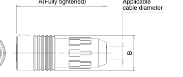
(Representative example)
| Part No. | HRS No. | A | B Ap | plicable cable diameter range | Solder pot inner diameter | Weight |
|---|---|---|---|---|---|---|
| HR30-6P-3S(31) | 130-0004-1 31 | 29.8 | 12.6 | 4.2 to 5 | 1.1 mm | 4g |
| HR30-6P-6S(31) | 130-0010-4 31 | 0.8 mm | ||||
| HR30-6P-6P(31) | 130-0009-5 31 | 30.3 | ||||
| HR30-6PA-3S(71) | 130-0021-0 71 | 29.8 | 3.5 to 4.3 | 1.1 mm | ||
| HR30-6PA-6S(71) | 130-0019-9 71 | 0.8 mm | ||||
| HR30-6PA-6P(71) | 130-0020-8 71 | 30.3 | ||||
| HR30-7P-12S(71) | 130-0027-7 71 | 39.8 | 15.5 | 6.2 to 7 | 0.6 mm | 6.7g |
| HR30-8P-12P(71) | 130-0026-4 71 |
Applicable
A(Fully tightened)
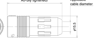
(Representative example)
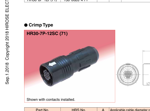
| Part No. | HRS No. | A | Applicable cable diameter range | Crimp contact | Weight |
|---|---|---|---|---|---|
| HR30-7P-10SC(71) | 130-0013-2 71 | 39.8 | 6.2 to 7 | HR30-SC-211 | 6g |
| HR30-7P-12SC(71) | 130-0014-5 71 | ||||
| HR30-8P-12PC(71) | 130-0015-8 71 | HR30-PC-211 |
Page 4
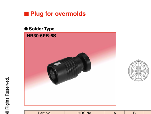
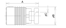
| Part No. | HRS No. | A | B | C | Solder pot inner diameter | Weight |
|---|---|---|---|---|---|---|
| HR30-6PB-3S | 130-0034-2 | 22.7 | 12.6 | 5.2 | 1.1 mm | 3.1g |
| HR30-6PB-6S | 130-0032-7 | 0.8 mm | 2.9g | |||
| HR30-6PB-6P | 130-0037-0 | 23.2 | ||||
| HR30-7PB-12S | 130-0035-5 | 25.9 | 15.5 | 6.4 | 0.6 mm | 4.7g |
| HR30-8PB-12P | 130-0030-1 | 4.5g |
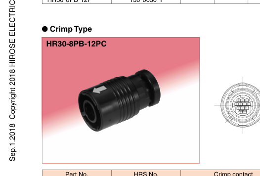
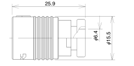
| Part No. | HRS No. | Crimp contact | Weight |
|---|---|---|---|
| HR30-7PB-10SC | 130-0036-8 | HR30-SC-211 | 4.1g |
| HR30-7PB-12SC | 130-0033-0 | ||
| HR30-8PB-12PC | 130-0031-4 | HR30-PC-211 | 4.3g |
Page 5
A
Gasket
5
E(Thread)
F(Hex nut)
(Representative example)
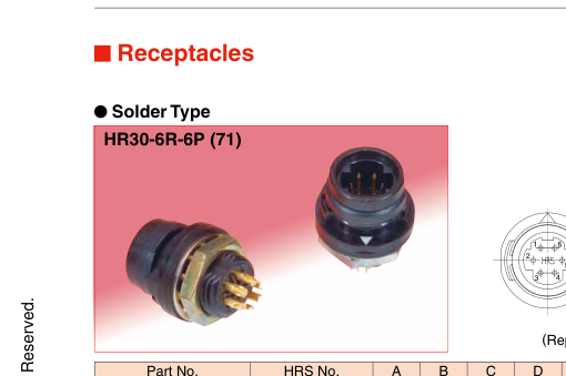
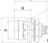
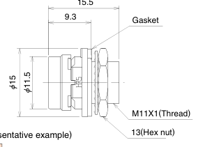
| Part No. | HRS No. | A | B | C | D E | F Solder p | ot inner diameter | Weight |
|---|---|---|---|---|---|---|---|---|
| HR30-6R-3P(71) | 130-1003-4 71 | 16 | 8.3 | 12 8 | .9 M8∞0.75 | 10 | 1.1mm | 2g |
| HR30-6R-6P(71) | 130-1009-0 71 | 0.8mm | ||||||
| HR30-6R-6S(71) | 130-1008-8 71 | 18.4 | ||||||
| HR30-7R-12P(31) | 130-1016-6 31 | 18.6 | 9.3 | 15 11 | .5 M11∞1 | 13 | 0.6mm | 3.4g |
| HR30-8R-12S(31) | 130-1018-1 31 |
| Part No. | HRS No. | Crimp contact | Weight |
|---|---|---|---|
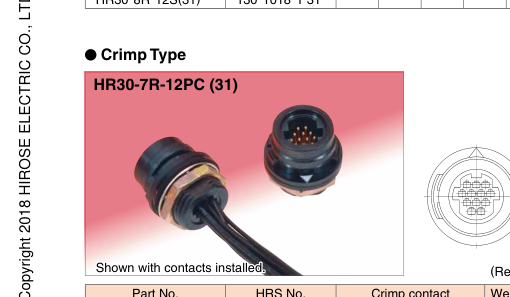
| HR30-7R-10PC(31) | 130-1012-5 31 | HR30-PC-211 | 3g |
| HR30-7R-12PC(31) | 130-1013-8 31 | ||
| HR30-8R-12SC(31) | 130-1014-0 31 | HR30-SC-211 |
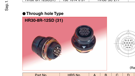
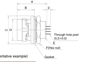
| Part No. | HRS No. | A | B | C | D E | F Weight |
|---|---|---|---|---|---|---|
| HR30-6R-6PD(71) | 130-1020-3 71 | 14.9 | 8.3 | 12 8 | .9 M8∞0.75 | 10 2g |
| HR30-6R-6SD(71) | 130-1021-6 71 | 15.2 | ||||
| HR30-7R-12PD(31) | 130-1017-9 31 | 16 | 9.3 | 15 11 | .5 M11∞1 | 13 3.4g |
| HR30-8R-12SD(31) | 130-1019-4 31 |
Page 6
Applicable
B(Fully tightened)
(Representative example)
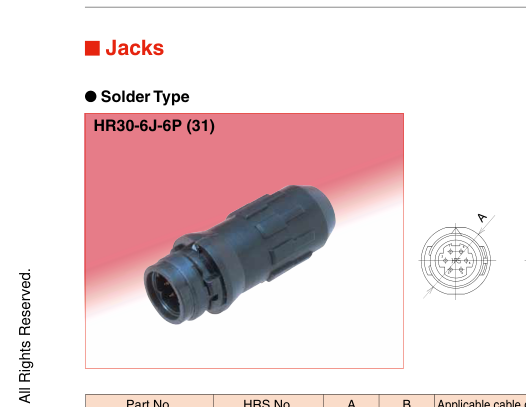
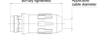
| Part No. | HRS No. | A | B Ap | plicable cable diameter range | Solder pot inner diameter | Weight |
|---|---|---|---|---|---|---|
| HR30-6J-6P(31) | 130-2009-6 31 | 12 | 28.8 | 4.2 to 5 | 0.8 mm | 3g |
| HR30-6JA-6P(71) | 130-2018-7 71 | 3.5 to 4.3 | ||||
| HR30-7J-12P(71) | 130-2020-9 71 | 15 | 37.3 | 6.2 to 7 | 0.6 mm | 5.7g |
| HR30-8J-12S(71) | 130-2019-0 71 | 5.9g |
37.3 (Fully tightened)
Applicable
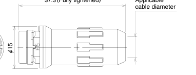
(Representative example)
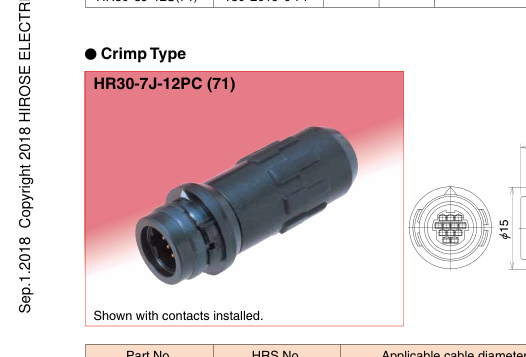
| Part No. | HRS No. | Applicable cable diameter range | Crimp contact | Weight |
|---|---|---|---|---|
| HR30-7J-10PC(71) | 130-2015-9 71 | 6.2 to 7 | HR30-PC-211 | 5g |
| HR30-7J-12PC(71) | 130-2017-4 71 | |||
| HR30-8J-12SC(71) | 130-2016-1 71 | HR30-SC-211 |
Page 7
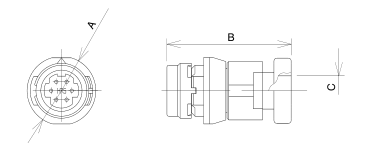
| Part No. | HRS No. | A | B | C | Solder pot inner diameter | Weight |
|---|---|---|---|---|---|---|
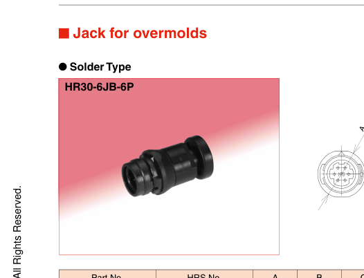
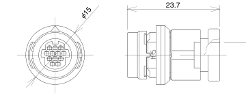
| HR30-6JB-3P | 130-2029-0 | 12.7 | 21.7 | 5.2 | 1.1mm | 2.3g |
| HR30-6JB-6P | 130-2021-1 | 12 | 0.8mm | 2.2g | ||
| HR30-6JB-6S | 130-2028-0 | 12.7 | 2.3g | |||
| HR30-7JB-12P | 130-2023-7 | 15 | 23.7 | 6.4 | 0.6mm | 3.6g |
| HR30-8JB-12S | 130-2024-0 | 4.1g |
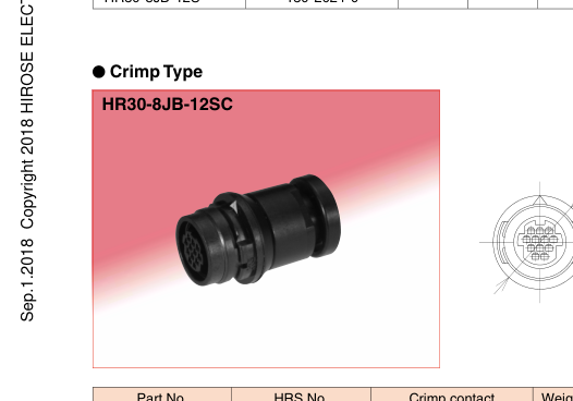
| Part No. | HRS No. | Crimp contact | Weight |
|---|---|---|---|
| HR30-7JB-10PC | 130-2025-2 | HR30-PC-211 HR30-SC-211 | 3.1g |
| HR30-7JB-12PC | 130-2022-4 | ||
| HR30-8JB-12SC | 130-2026-5 |
Page 8
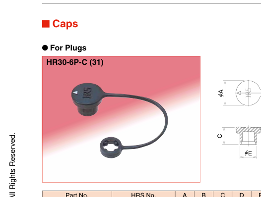
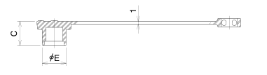
(Representative example)
| Part No. | HRS No. | A | B | C | D | E Applicable cable diameter | Weight |
|---|---|---|---|---|---|---|---|
| HR30-6P-C(31) | 130-3000-7 31 | 13 | 8.4 | 8.9 | 4 | 8.8 Ø4.2 to 5 | 1g |
| HR30-7P-C(31) | 130-3004-8 31 | 16 | 10.4 | 10.5 | 6 1 | 1.4 Ø6.2 to 7 | 2g |
| HR30-8P-C(31) | 130-3003-5 31 |
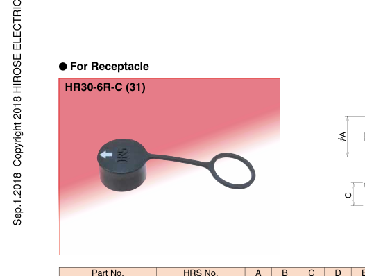
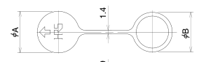
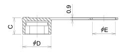
(Representative example)
| Part No. | HRS No. | A | B | C | D | E Remarks | Weight |
|---|---|---|---|---|---|---|---|
| HR30-6R-C(31) | 130-3001-0 31 | 12.6 | 11.8 | 7.5 | 12.1 | 9.1 | 1g |
| HR30-7R-C(31) | 130-3002-2 31 | 15.5 | 14.8 | 8.5 | 15 1 | This cap fi ts each size of 2.1 the HR30-7R and HR30-8R receptacles |
Note : When using these caps, do not use the gasket that is normally supplied with the receptacle. The “B” diameter end of the receptacle cap will serve as the gasket.
Page 9
Crimp Contacts
Male contact
Female contact
1.2
1.2
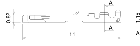
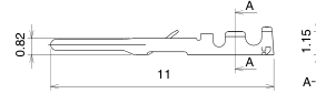
A-A cross-section
(Representative example)
A-A cross-section
(Representative example)
| Type | Part No. | HRS No. | Packaging type | Weight |
|---|---|---|---|---|
| Loose contact | HR30-SC-111 | 130-0023-6 | 100pcs/pack | 0.03g/1 pin |
| Reel contact | HR30-SC-211 | 130-0017-3 | 10,000pcs/reel | 0.03g/1 pin |
| Type | Part No. | HRS No. | Packagin type | g Weight |
|---|---|---|---|---|
| Loose contact | HR30-PC-111 | 130-0022-3 | 100pcs/pac | k 0.03g/1 pin |
| Reel contact | HR30-PC-211 | 130-0016-0 | 10,000pcs/r | eel 0.03g/1 pin |
Note : Use wire size 26 to 30 AWG with a jacket diameter of 1 mm max.
Diagrams of Connectors in Combination
Plugs
Receptacles
HR30-\*P-\*\*(71)
HR30-\*R-\*\*(71)
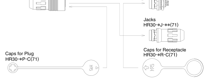
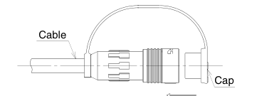
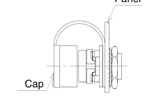
Note 1 : Please use connectors with compatible shell size and number of contacts. If you are using a male contact plug, please also use a corresponding product with a female receptacle and a jack. Note 2 : Please install the applicable crimping contacts when using the crimping style connectors. (Please refer to the manual for wiring work.) Note 3 : When using the cap on the receptacle side, do not use the gasket that is normally supplied with the receptacle. The Hirose cap has the necessary gasket as part of the cap unit.
Cap mounting diagram
Panel
Page 10
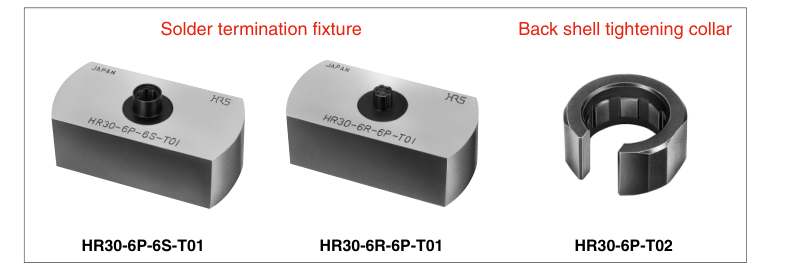
Applicable Tools
Cable Assembly Tools
| Part No. | HRS No. | Applicable Connectors | |||
|---|---|---|---|---|---|
| Shell size | Connector type | No. of contacts | Contact type | ||
| HR30-6P-3S-T01 | 150-0220-1 | 6 | Plug | 3 | Female |
| HR30-6P-6S-T01 | 150-0214-9 | 6 | Female | ||
| HR30-6P-6P-T01 | 150-0221-4 | Male | |||
| HR30-7P-10SC-T01 | 150-0228-3 | 7 | Plug | 10 | Female |
| HR30-7P-12SC-T01 | 150-0223-0 | 12 | Female | ||
| HR30-8P-12PC-T01 | 150-0227-0 | 8 | Plug | 12 | Male |
| HR30-6R-3P-T01 | 150-0225-5 | 6 | Receptacle Jack | 3 | Male |
| HR30-6R-6P-T01 | 150-0218-0 | 6 | Male | ||
| HR30-6R-6S-T01 | 150-0222-7 | Female | |||
| HR30-7J-10PC-T01 | 150-0231-8 | 7 | Receptacle Jack | 10 | Male |
| HR30-7J-12PC-T01 | 150-0230-5 | 12 | Male | ||
| HR30-8J-12SC-T01 | 150-0226-8 | 8 | Female | ||
Note : Wiring for soldering or disassembly and assembly of plugs and jacks can be accomplished more effi ciently when using the cable assembly tool.
Tightening collar for back shell
| Part No. | HRS No. | Applicable Connectors |
|---|---|---|
| HR30-6P-T02 | 150-0216-4 | 3 and 6 contacts |
| HR30-8P-T02 | 150-0224-2 | 10 and 12 contacts |
Note : The code ring tightening collar is used to tighten the cord ring to the specifi ed torque. (Please refer to the manual for assembly procedures.)
Page 11
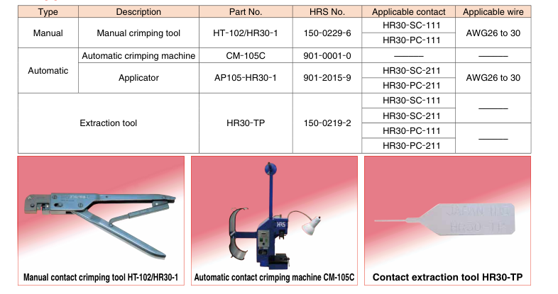
Applicable Tools
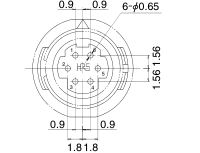
Receptacle, Board Mounting Through Hole Pattern
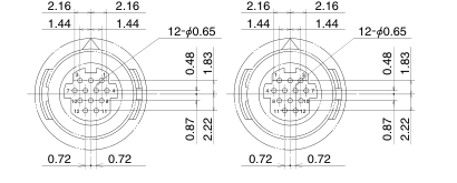
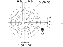
6R-6PD
6R-6SD
7R-12PD
8R-12SD
Remark : 1. The receptacle through hole confi guration depicts a view from the mating side of the connector. 2.The above Δ mark indicates the guide key position. 3.The recommended board maximum thickness :1.2mm. 4. Tolerance of +0.03mm is recommended for the plated through hole location. Tolerance of +0.02mm is recommended for the plated through hole diameter.
Contact Position Arrangement
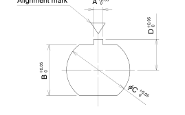
Panel Cutout
Alignment mark
Alignment mark
+0.05
1 6
5 1
1 3
6
2 5
4 2 3
3 4
2
HR30-6P-3S(\*\*)
HR30-6P-6S(\*\*)
HR30-6P-6P(\*\*)
1 2 3
3 2 1
3 2 1
4 5 6 7
7 6 5 4
7 6 5 4
| A | B C | D | Panel Thishness | |
| 3,6 pos. | 1.25 | 6.45 8. | 05 3.95 | 0.7 to 2 |
| 10,12 pos. | 1.35 | 9.25 11. | 05 5.45 | 0.7 to 3 |
8 9 10
10 9 8
10 9 8
12 11
11 12
HR30-7P-10SC(\*\*) HR30-7P-12SC(\*\*) HR30-8P-12PC(\*\*)
Remarks : 1. The contact arrangement depicts a view from the wiring side. 2. Installation is accomplished by securing the receptacle from the back side of the panel using the supplied hexagon nut. The tightening torque of the hexagon nut should be 0.5 N·m for 3, 6 contacts, and 0.8 N·m for 10, 12 contacts.
In addition, in order to prevent loosening, please apply Locktight 263 and Lockprimer 7649 manufactured by Henkel Japan Ltd., Tokyo.
Page 12
Assembly Procedures
| Plug Assembly Sequence | |
| 1 | Push/pull locking collar Seal bushing Insulator/contact assembly Back shell Spring Strain relief A B Cable A B Solder type : 3 and 6 Contacts. 2mm 5.5mm max. Solder type : 12 Contacts. 2mm 10mm max. Crimp type : 10 and 12 Contacts. 2 --0 0.5mm 15 to 20mm |
| Insert the cable in the following order : 1. Back shell, 2. cord clamp, 3. gasket, 4, spring and 5. locking collar. Prepare the cable end according to the dimensions shown in Table 1. Note : When preparing the cable, use caution not to damage the insulation and conductors of the lead wires. | |
| 2 | Block end face Insulator/contact assembly Solder termination fixture |
| Solder type Fix the P case block on the cable termination tool, and after preliminary soldering, solder for 3 to 4 seconds with the soldering iron at 350±10ç. Note 1 : T ake care to avoid creating cold solder joints and solder joints with voids or air holes in it. Also check to make sure the solder joint is adequately fused between the lead wires and solder cup. Note 2 : The P case block is a precision unit. Please use caution when soldering the P case block so it does not become damaged. Any damage could result in loss of the waterproof performance. Crimp type After crimping the appropriate contact to the cable lead wire, insert the terminated wire into the correct contact position on the P case block. Note : A fter inserting the crimping wire/contact, slightly pull the lead wire and check if the crimping contact is properly seated into the P case block. | |
| A | B | |
| der type : 3 and 6 Contacts. | 2mm | 5.5mm max. |
| der type : 12 Contacts. | 2mm | 10mm max. |
| mp type : 10 and 12 Contacts. | 2 --0 0.5mm | 15 to 20mm |
Page 13
| 3 | Fixation Cable Push/pull Back shell Cable locking collar Guide keys Tightening collar for back shell A (Refer to Table-2) Plug insulator body Solder termination fixture Cable View A (2:1) Groove - sealing bushing Front edge of cable jacket Fig.B Fig.C Table-2 Connector Back shell tightening collar size Torque 3 and 6 Contacts. 16mm 0.5N.m 10 and 12 Contacts. 18mm 0.5N.m |
|---|---|
| Insert the cable by fitting the coupling guide to the wire-connected P case block. Then, pass the cable through and assemble in the following order: 1. spring, gasket, 2 cord clamp, and 3. cord tube. Make sure when assembling it with the cord clamp and cord tube, to maintain the positional relations between the cable sheath end face and the concave area of the gasket as shown in Fig.B. Note : Please install the cord tube using the cord tube tightening tool with the cord ring tightening torque shown in Table-2. ln addition, in order to prevent loosening, please apply Locktight 263 and Lockprimer 7649 manufactured by Henkel Japan Ltd., Tokyo. When screwing in the cord tube, use your hand to hold the cable so that the cable will not rotate or twist and apply stress to the soldered wires. However, as the cable tends to be twisted slightly (just over one rotation), we recommend that you twist it in the opposite direction in advance. |
| Back shell tightening collar size | Torque |
| 16mm | 0.5N.m |
| 18mm | 0.5N.m |
Page 14
Points to note when using Heat shrink tubing
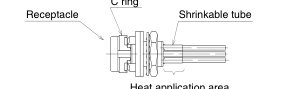
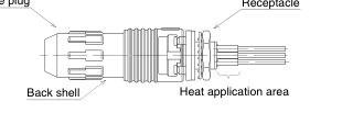
We recommend that you use shrink tubing over the solder connections in order to protect the soldered wires and to enhance insulation. However, please be careful when applying heat in this area when installing the shrink tube so excess heat does not bleed into or affect the resin parts as shown in the figure below.
If the product does become heated beyond the area shown and into the resin parts, please make sure to prevent the following. q Deformation of the C ring. This could result in prevention of locking during mating. w Melting of some parts. To prevent the deformation of the C rings of the receptacles and the jack, we recommend heat to be applied after mating with a compatible plug. Before heating, please mate the plug in the receptacle securely, then pull the back shell for checking whether it is locked properly. If it is heated with semi-fitting, C ring may be thermally deformed with shrinking condition and it may not be locked properly.
C ring
Heat application area
Mated dimensions
Compatible plug
Receptacle
Page 15
General usage notes
| 1. Mating | 2. Un-mating |
| Mounting panel Receptacle Cable D Plug C A D Alignment marks C | Mounting panel Push/pull locking collar Cable B |
| When mounting, smooth mating will be achieved by holdi plug in any are “A” and aligning the arrow of the plug with that of the receptacle, then pushing the plug straight in. | ng When removing the plug from its connected condition, hold the plug by push/pull locking collar (area “B”) and pull straight off. |
Precautions
- Make sure the power is off before mating or un-mating the connector. 2. When mating the connector, push it on with a force of a least 30N. After mating, pull slightly on the connector to check for proper mating and to ensure the connector is fi rmly locked to the receptacle. 3. After mating the connector, do not apply a force over 30N to the cable in the directions shown by the arrows. An excessive load can lead to connector damage.
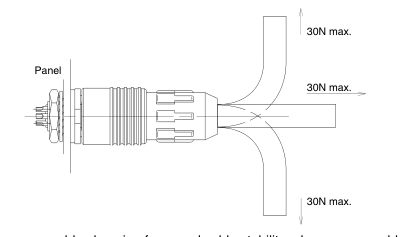
- To maintain the waterproof performance, cable clamping force and cable stability, please use a cable within the recommended for cable diameters. Because the performance will differ depending on the cable structure, make sure to check all specifi cations of the cable assembly before use or production. 5. Please assemble and install the connector and components with the specifi ed tightening torque. If the tightening torque is too weak or too strong, loosening or breakage can occur. 6.Please contact Hirose if your application requires compliance with the Electrical Appliance and Meterial Safety Act.
Page 16
USA:
USA:
HIROSE ELECTRIC (U.S.A.), INC. HEADQUARTERS CHICAGO OFFICE HIROSE ELECTRIC (U.S.A.), INC. SAN JOSE OFFICE
2300 Warrenville Road, Suite 150,
2841 Junction Ave, Suite 200
Downers Grove, IL 60515
San Jose, CA. 95134
Phone : +1-630-282-6700
Phone : +1-408-253-9640
http://www.hirose.com/us/
Fax : +1-408-253-9641 http://www.hirose.com/us/
USA:
THE NETHERLANDS:
HIROSE ELECTRIC (U.S.A.), INC. BOSTON OFFICE HIROSE ELECTRIC EUROPE B.V.
300 Brickstone Square Suite 201,
Hogehillweg #8 1101 CC Amsterdam Z-O
Andover, MA 01810
Phone : +31-20-6557460
Phone : +1-978-662-5255
Fax : +31-20-6557469 http://www.hirose.com/eu/
GERMANY:
GERMANY:
HIROSE ELECTRIC EUROPE B.V. NUREMBERG OFFICE HIROSE ELECTRIC EUROPE B.V. HANOVER OFFICE
Neumeyerstrasse 22-26, 90411 Nurnberg
Bayernstr. 3, Haus C 30855 Langenhagen, Germany Phone : +49-511 97 82 61 30
Phone : +49-911 32 68 89 63
Fax : +49-511 97 82 61 35
Fax : +49-911 32 68 89 69
http://www.hirose.com/eu/
http://www.hirose.com/eu/
UNITED KINGDOM:
CHINA:
HIROSE ELECTRIC (CHINA) CO., LTD. (SHANGHAI, HEADQUARTERS)
HIROSE ELECTRIC EUROPE BV (UK BRANCH)
18, Enterprise Center Tower 2, 209# Gong He
4 Newton Court, Kelvin Drive, Knowlhill,
Road, Jing’an District, Shanghai, CHINA 200070
Milton Keynes, MK5 8NH
Phone : +86-21-6391-3355
Phone : +44-1908 202050
Fax : +86-21-6391-3335
Fax : +44-1908 202058
http://www.hirose.com/cn/
http://www.hirose.com/eu/
CHINA:
HONG KONG:
HIROSE ELECTRIC (CHINA) CO., LTD. SHENZHEN BRANCH HIROSE ELECTRIC HONGKONG TRADING CO., LTD.
Room 09-13, 19/F, Office Tower Shun Hing Square, Di Wang Commercial Centre, Room 1001, West Wing, Tsim Sha Tsui Centre, 66
Mody Road, Tsim Sha Tsui East, Kowloon, Hong Kong
5002 Shen Nan Dong Road, Shenzhen City, Guangdong Province, 518008 Phone : +86-755-8207-0851
Phone : +852-2803-5338
Fax : +86-755-8207-0873
Fax : +852-2591-6560
http://www.hirose.com/cn/
http://www.hirose.com/hk/
SINGAPORE:
KOREA:
HIROSE ELECTRIC SINGAPORE PTE. LTD.
HIROSE KOREA CO.,LTD.
143, Gongdan 1-daero, Siheung-si,
03, Anson Road, #20-01, Springleaf Tower,
Gyeonggi-do, 15084, Korea
Singapore 079909
Phone : +82-31-496-7000
Phone : +65-6324-6113 Fax : +65-6324-6123
Fax : +82-31-496-7100
http://www.hirose.com/sg/
http://www.hirose.co.kr/
MALAYSIA:
INDIA:
HIROSE ELECTRIC SINGAPORE PTE. LTD. BANGALORE LIAISON OFFICE PENANG REPRESENTATIVE OFFICE
Unit No-403, 4th Floor, No-84, Barton Centre, Mahatma 73-3-1, Ideal@The One, Jalan Mahsuri, Bayan Gandhi (MG) Road, Bangalore 560 001, Karnataka, India
Lepas Penang, 11950, Malaysia
Phone : +91-80-4120 1907
Phone : +604-648-5536
Fax : +91-80-4120 9908
http://www.hirose.com/sg/
http://www.hirose.com/sg/

USA:
HIROSE ELECTRIC (U.S.A.), INC. DETROIT OFFICE (AUTOMOTIVE)
17197 N. Laurel Park Drive, Suite 253, Livonia, MI 48152 Phone : +1-734-542-9963 Fax : +1-734-542-9964 http://www.hirose.com/us/
GERMANY: HIROSE ELECTRIC EUROPE B.V. GERMAN BRANCH
Schoenbergstr. 20, 73760 ostfildern Phone : +49-711-456002-1 Fax : +49-711-456002-299 http://www.hirose.com/eu/
FRANCE: HIROSE ELECTRIC EUROPE B.V. PARIS OFFICE
130 Avenue Joseph Kessel, Bat E, 78960 Voisins le Bretonneux, France Phone : +33-1-85764886 Fax : +33-1-85764823 http://www.hirose.com/eu/
CHINA: HIROSE ELECTRIC (CHINA) CO.,LTD. BEIJING BRANCH
A1001, Ocean International Center, Building 56# East 4th Ring Middle Road, ChaoYang District, Beijing, 100025 Phone : +86-10-5165-9332 Fax : +86-10-5908-1381 http://www.hirose.com/cn/
TAIWAN: HIROSE ELECTRIC TAIWAN CO., LTD.
103 8F, No.87, Zhengzhou Rd., Taipei Phone : +886-2-2555-7377 Fax : +886-2-2555-7355 http://www.hirose.com/tw/
INDIA:
HIROSE ELECTRIC SINGAPORE PTE. LTD. DELHI LIAISON OFFICE
Office NO.552, Regus-Green Boulevard, Level5, Tower C, Sec62, Plot B-9A, Block B, Noida, 201301, Uttar Pradesh, India Phone : +91-12-660-8018 Fax : +91-120-4804949 http://www.hirose.com/sg/
THAILAND: BANGKOK OFFICE (REPRESENTATIVE OFFICE)
Unit 4703, 47th FL., 1 Empire Tower, South Sathorn Road, Yannawa, Sathorn, Bangkok 10120 Thailand Phone : +66-2-686-1255 Fax : +66-2-686-3433 http://www.hirose.com/sg/
2-6-3,Nakagawa Chuoh,Tsuzuki-Ku,Yokohama-Shi 224-8540,JAPAN TEL: +81-45-620-3526 Fax: +81-45-591-3726 http://www.hirose.com http://www.hirose-connectors.com
The characteristics and the specifications contained herein are for reference purpose. Please refer to the latest customer drawings prior to use. The contents of this catalog are current as of date of 06/2018. Contents are subject to change without notice for the purpose of improvements.