


 Download PDF
HL3P-6xC0-000xx ABRACON
Document overview
- PDF pages: 9
Technical content
Page 1
Data Sheet
HL3P-6xC0-000xx
3-mm Round, 3-Leads Auto-Insertable Bicolor LED Lamp
Overview
The Broadcom® HL3P-6xC0-000xx are bicolor LEDs available in the industry-popular T1 through-hole lamp package. These LEDs use high brightness AlInGaP chip technology and offer high light output. They are available in multiple color combinations, such as Red/Yellow-Green and Yellow/Yellow-Green.
These LEDs have an untinted, diffused epoxy body and come with a 45 degree viewing angle. They are easy to use, which makes them an ideal choice for a wide variety of applications such as status indicators in industrial and commercial segments.
These LEDs are available in ammo-packing and support machine auto-insertion.
Features
Available in Red/Yellow-Green and Yellow/Yellow- Green color combinations High brightness Low power consumption Support machine auto-insertion Available in ammo-packing
Applications
Status indicators Industrial/Consumer electronics Home appliances
CAUTION! This product is Class 1B HBM ESD sensitive per JEDEC Standard. Observe appropriate precautions during
handling and processing. Refer to Application Note 1142 for additional details.
September 4, 2024
Page 2
Figure 1: Package Drawing
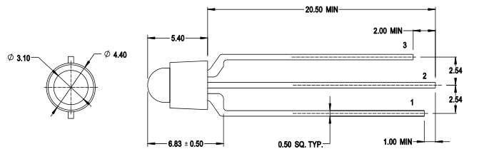
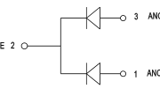
NOTE:
- All dimensions in millimeters (mm). 2. Tolerance is ±0.3 mm unless otherwise specified. 3. Epoxy meniscus may extend up to maximum 1 mm down the leads. 4. Lead spacing is measured at where the leads emerge from the body.
Device Selection Guide (TJ = 25°C, IF = 20 mA)

a. The luminous intensity, IV, is measured at the mechanical axis of the package, and it is tested with a single current pulse condition. b. The optical axis is closely aligned with the mechanical axis of the package. c. Tolerance is ±15%. d. θ½ is the off-axis angle where the luminous intensity is half of the peak intensity.
Page 3
Absolute Maximum Ratings
| Parameters | Rating | Unit |
|---|---|---|
| DC Forward Current a | 25 | mA |
| Peak Forward Current b | 60 | mA |
| Power Dissipation | 63 | mW |
| LED Junction Temperature | 100 | °C |
| Operating Temperature Range | –40 to +85 | °C |
| Storage Temperature Range | –40 to +85 | °C |
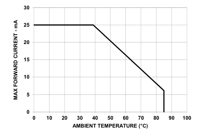
a. Derate linearly as shown in Figure 6. b. Duty factor = 10%, frequency = 1 kHz.
Optical and Electrical Characteristics (TJ = 25°C, IF = 20 mA)
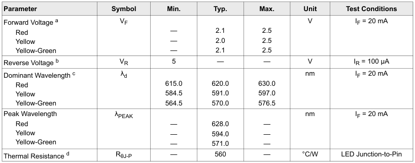
a. Forward voltage tolerance is ±0.1V. b. Indicates product final test condition. Long-term reverse bias is not recommended. c. The dominant wavelength, λd, is derived from the CIE Chromaticity Diagram and represents the perceived color of the device. d. Thermal resistance from LED junction to pin
Page 4
Part Numbering System
H L 3 P – 6
x1 x2 0 – 0 0 0
x3 x4
| Code | Description | Option | |
|---|---|---|---|
| x 1 | Color Combination | 1 | Red/Yellow-Green |
| 2 | Yellow/Yellow-Green | ||
| x 2 | Pin Configuration | C | Common Cathode |
| x x 3 4 | Packaging Option | 00 | Bulk |
| MC | Ammopack with Dimension H 20.0 mm | ||
Page 5
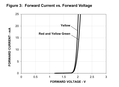
Figure 2: Spectral Power Distribution
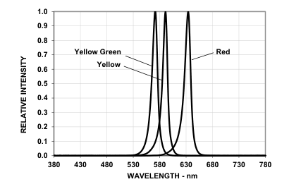
Figure 4: Relative Luminous Intensity vs. Mono Pulse Current
Figure 5: Radiation Pattern
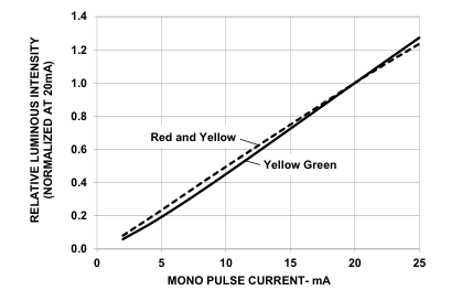
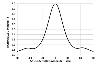
Figure 6: Maximum Forward Current vs. Ambient Temperature
Page 6
Figure 7: Tape Outline Drawing – For Packaging Option MC
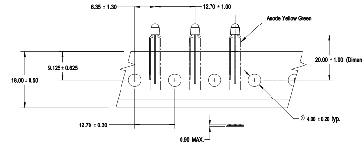
NOTE: All dimensions are in millimeters.
Figure 8: Packaging Box for Ammopack
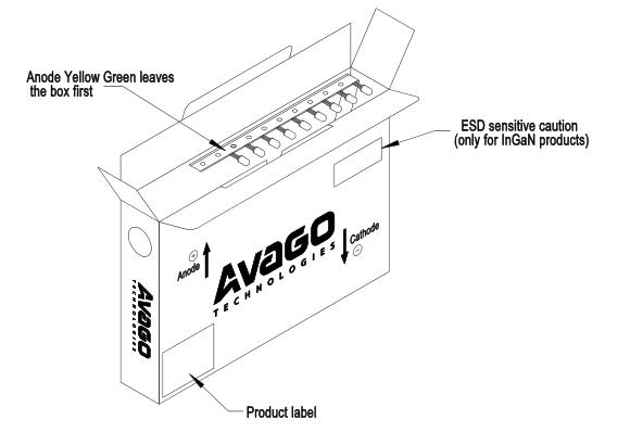
Page 7
Precautionary Notes
Soldering and Handling Precautions
Set and maintain the wave soldering parameters according to the recommended temperature and dwell time. Perform a daily check on the profile to ensure that it always conforming to the recommended conditions. Exceeding these conditions will overstress the LEDs and cause premature failures. Use only bottom preheaters to reduce thermal stress experienced by the LEDs. Recalibrate the soldering profile before loading a new type of PCB. A PCB with a different size and design (component density) will have a different heat capacity and might cause a change in the temperature experienced by the PCB if the same wave soldering setting is used. Do not perform wave soldering more than once.
Any alignment fixture used during wave soldering must be loosely fitted and must not apply stress on the LEDs. Use a nonmetal material because it will absorb less heat during the wave soldering process. At elevated temperature, the LEDs are more susceptible to mechanical stress. Allow the PCB to sufficiently cool to room temperature before handling. Do not apply stress to the LED when it is hot. Use wave soldering to solder the LED. Use hand soldering only for rework or touch-up if unavoidable, but it must be strictly controlled to the following conditions: – Soldering iron tip temperature = 350°C maximum – Soldering duration = 3 seconds maximum – Number of cycles = 1 only
– Power of soldering iron = 50W maximum For ESD-sensitive devices, apply proper ESD precautions at the soldering station. Use only an ESDsafe soldering iron. Do not touch the LED package body with the soldering iron except for the soldering terminals because it might cause damage to the LED. Confirm beforehand whether the functionality and performance of the LED are affected by hand soldering. Keep the heat source at least 1.6 mm away from the LED body during soldering. Design an appropriate hole size to avoid problems during insertion or clinching (for auto-insertable devices).
Figure 9: Recommended PCB Through-Hole Size
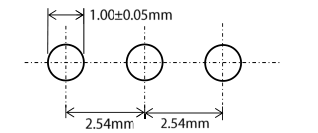
Figure 10: Recommended Wave Soldering Profile
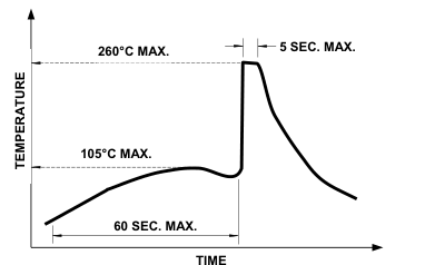
NOTE: Refers to measurements with a thermocouple
mounted at the bottom of the PCB.
Refer to Application Note 5334 for more information on soldering and handling of TH LED lamp.
Page 8
Application Precautions
The drive current of the LED must not exceed the maximum allowable limit across temperature as stated in the data sheet. Constant current driving is recommended to ensure consistent performance. Circuit design must cater to the whole range of forward voltage (VF) of the LEDs to ensure that the intended drive current can always be achieved. The LED exhibits slightly different characteristics at different drive currents, which might result in a larger variation of performance (that is, intensity, wavelength, and forward voltage). Set the application current as close as possible to the test current to minimize these variations. The LED is not intended for reverse bias. Use other
appropriate components for such purposes. When driving the LED in matrix form, ensure that the reverse bias voltage does not exceed the allowable limit of the LED. Avoid rapid changes in ambient temperature, especially in high-humidity environments, because they cause condensation on the LED.
Eye Safety Precautions
LEDs may pose optical hazards when in operation. Do not look directly at operating LEDs because it might be harmful to the eyes. For safety reasons, use appropriate shielding or personal protective equipment.
Page 9
Disclaimer
Broadcom’s products and software are not specifically designed, manufactured, or authorized for sale as parts, components, or assemblies for the planning, construction, maintenance, or direct operation of a nuclear facility or for use in medical devices or applications. The customer is solely responsible, and waives all rights to make claims against Broadcom or its suppliers, for all loss, damage, expense, or liability in connection with such use.
Copyright © 2024 Broadcom. All Rights Reserved. The term “Broadcom” refers to Broadcom Inc. and/or its subsidiaries. For more information, go to www.broadcom.com. All trademarks, trade names, service marks, and logos referenced herein belong to their respective companies.
Broadcom reserves the right to make changes without further notice to any products or data herein to improve reliability, function, or design. Information furnished by Broadcom is believed to be accurate and reliable. However, Broadcom does not assume any liability arising out of the application or use of this information, nor the application or use of any product or circuit described herein, neither does it convey any license under its patent rights nor the rights of others.
Lead (Pb) Free RoHS Compliant