


 Download PDF
HGTG40N60C3 FAIRCHILD
Document overview
- PDF pages: 8
Technical content
Page 1
Data Sheet
75A, 600V, UFS Series N-Channel IGBT
The HGTG40N60C3 is a MOS gated high voltage switching device combining the best features of a MOSFET and a bipolar transistor. These devices have the high input impedance of a MOSFET and the low on-state conduction loss of a bipolar transistor. The much lower on-state voltage drop varies only moderately between 25oC and 150oC.
The IGBT is ideal for many high voltage switching applications operating at moderate frequencies where low conduction losses are essential, such as: AC and DC motor controls, power supplies and drivers for solenoids, relays and contactors.
Formerly developmental type TA49273.
Ordering Information
| PART NUMBER | PACKAGE | PKG. NO. |
|---|---|---|
| HGTG40N60C3 | TO-247 | G40N60C3 |
NOTE: When ordering, use the entire part number.
Symbol
C
G
E
December 2001
Features
- 75A, 600V, TC = 25oC
- 600V Switching SOA Capability
- Typical Fall Time. . . . . . . . . . . . . . . . 100ns at TJ = 150oC
- Short Circuit Rating
- Low Conduction Loss
Packaging
JEDEC STYLE TO-247
E C G
FAIRCHILD CORPORATION IGBT PRODUCT IS COVERED BY ONE OR MORE OF THE FOLLOWING U.S. PATENTS
4,364,073
4,417,385
4,430,792
4,443,931
4,466,176
4,516,143
4,532,534
4,587,713
4,598,461
4,605,948
4,620,211
4,631,564
4,639,754
4,639,762
4,641,162
4,644,637
4,682,195
4,684,413
4,694,313
4,717,679
4,743,952
4,783,690
4,794,432
4,801,986
4,803,533
4,809,045
4,809,047
4,810,665
4,823,176
4,837,606
4,860,080
4,883,767
4,888,627
4,890,143
4,901,127
4,904,609
4,933,740
4,963,951
4,969,027
Page 2
| Absolute Maximum Ratings TC = 25oC, Unless Otherwise Specified HGTG40N60C3 UNITS Collector to Emitter Voltage . . . . . . . . . . . . . . . . . . . . . . . . . . . . . . . . . . . . . . . . . . . . . .BVCES 600 V Collector Current Continuous At TC = 25oC . . . . . . . . . . . . . . . . . . . . . . . . . . . . . . . . . . . . . . . . . . . . . . . . . . . . . . . . . IC25 75 A At TC = 110oC . . . . . . . . . . . . . . . . . . . . . . . . . . . . . . . . . . . . . . . . . . . . . . . . . . . . . . . IC110 40 A Collector Current Pulsed (Note 1) . . . . . . . . . . . . . . . . . . . . . . . . . . . . . . . . . . . . . . . . . . . ICM 300 A Gate to Emitter Voltage Continuous. . . . . . . . . . . . . . . . . . . . . . . . . . . . . . . . . . . . . . . . . VGES ±20 V Gate to Emitter Voltage Pulsed . . . . . . . . . . . . . . . . . . . . . . . . . . . . . . . . . . . . . . . . . . . .VGEM ±30 V Switching Safe Operating Area at TJ = 150oC (Figure 2) . . . . . . . . . . . . . . . . . . . . . . . SSOA 40A at 600V Power Dissipation Total at TC = 25oC . . . . . . . . . . . . . . . . . . . . . . . . . . . . . . . . . . . . . . . . . PD 291 W Power Dissipation Derating TC > 25oC . . . . . . . . . . . . . . . . . . . . . . . . . . . . . . . . . . . . . . . . . . 2.33 W/oC Reverse Voltage Avalanche Energy. . . . . . . . . . . . . . . . . . . . . . . . . . . . . . . . . . . . . . . . . EARV 100 mJ Operating and Storage Junction Temperature Range . . . . . . . . . . . . . . . . . . . . . . . . TJ, TSTG -55 to 150 oC Maximum Lead Temperature for Soldering . . . . . . . . . . . . . . . . . . . . . . . . . . . . . . . . . . . . . TL 260 oC Short Circuit Withstand Time (Note 2) at VGE = 12V. . . . . . . . . . . . . . . . . . . . . . . . . . . . . .tSC 5 µs Short Circuit Withstand Time (Note 2) at VGE = 10V. . . . . . . . . . . . . . . . . . . . . . . . . . . . . .tSC 10 µs CAUTION: Stresses above those listed in “Absolute Maximum Ratings” may cause permanent damage to the device. This is a stress only rating and operation of the device at these or any other conditions above those indicated in the operational sections of this specification is not implied. NOTES: 1. Pulse width limited by maximum junction temperature. 2. VCE(PK) = 360V, TJ = 125oC, RG = 3Ω. | |||||||
|---|---|---|---|---|---|---|---|
| Electrical Specifications TC = 25oC, Unless Otherwise Specified | |||||||
| PARAMETER | SYMBOL | TEST CONDITIONS | MIN | TYP | MAX | UNITS | |
| Collector to Emitter Breakdown Voltage | BVCES | IC = 250µA, VGE = 0V | 600 | - | - | V | |
| Emitter to Collector Breakdown Voltage | BVECS | IC = 10mA, VGE = 0V | 15 | 25 | - | V | |
| Collector to Emitter Leakage Current | ICES | VCE = BVCES | TC = 25oC | - | - | 250 | µA |
| TC = 150oC | - | - | 4.0 | mA | |||
| Collector to Emitter Saturation Voltage | VCE(SAT) | IC = IC110, VGE = 15V | TC = 25oC | - | 1.3 | 1.8 | V |
| TC = 150oC | - | 1.4 | 2.0 | V | |||
| Gate to Emitter Threshold Voltage | VGE(TH) | IC = 250µA, VCE = VGE | 3.1 | 4.5 | 6.0 | V | |
| Gate to Emitter Leakage Current | IGES | VGE = ±20V | - | - | ±250 | nA | |
| Switching SOA | SSOA | TJ = 150oC, RG = 3Ω, VGE = 15V, L = 400µH | VCE = 480V | 200 | - | - | A |
| VCE = 600V | 40 | - | - | A | |||
| Gate to Emitter Plateau Voltage | VGEP | IC = IC110, VCE = 0.5 BVCES | - | 7.2 | - | V | |
| On-State Gate Charge | QG(ON) | IC = IC110, VCE = 0.5 BVCES | VGE = 15V | - | 275 | 302 | nC |
| VGE = 20V | - | 360 | 395 | nC | |||
| Current Turn-On Delay Time | td(ON)I | IGBT and Diode at TJ = 25oC ICE = IC110 VCE = 0.8 BVCES VGE = 15V RG = 3Ω L = 1mH Test Circuit (Figure 17) | - | 47 | - | ns | |
| Current Rise Time | trI | - | 30 | - | ns | ||
| Current Turn-Off Delay Time | td(OFF)I | - | 185 | - | ns | ||
| Current Fall Time | tfI | - | 60 | - | ns | ||
| Turn-On Energy (Note 3) | EON1 | - | 850 | - | mJ | ||
| Turn-On Energy (Note 3) | EON2 | - | 1.0 | 1.2 | mJ | ||
| Turn-Off Energy (Note 4) | EOFF | - | 1.0 | 1.8 | mJ | ||
Page 3
| Electrical Specifications TC = 25oC, Unless Otherwise Specified (Continued) | ||||||
| PARAMETER | SYMBOL | TEST CONDITIONS | MIN | TYP | MAX | UNITS |
| Current Turn-On Delay Time | td(ON)I | IGBT and Diode at TJ = 150oC ICE = IC110 VCE = 0.8 BVCES VGE = 15V RG = 3Ω L = 1mH Test Circuit (Figure 17) | - | 41 | - | ns |
| Current Rise Time | trI | - | 30 | - | ns | |
| Current Turn-Off Delay Time | td(OFF)I | - | 360 | 450 | ns | |
| Current Fall Time | tfI | - | 100 | 210 | ns | |
| Turn-On Energy (Note 3) | EON1 | - | 860 | - | µJ | |
| Turn-On Energy (Note 3) | EON2 | - | 2.0 | 2.4 | mJ | |
| Turn-Off Energy (Note 4) | EOFF | - | 2.5 | 4 | mJ | |
| Thermal Resistance Junction To Case | RθJC | - | - | 0.43 | oC/W | |
| NOTES: 3. Values for two Turn-On loss conditions are shown for the convenience of the circuit designer. EON1 is the turn-on loss of the IGBT only. EON2 is the turn-on loss when a typical diode is used in the test circuit and the diode is at the same TJ as the IGBT. The diode type is specified in Figure 17. 4. Turn-Off Energy Loss (EOFF) is defined as the integral of the instantaneous power loss starting at the trailing edge of the input pulse and ending at the point where the collector current equals zero (ICE = 0A). All devices were tested per JEDEC Standard No. 24-1 Method for Measurement of Power Device Turn-Off Switching Loss. This test method produces the true total Turn-Off Energy Loss. Typical Performance Curves Unless Otherwise Specified 80 225 (A) VGE = 15V TJ = 150oC, RG = 3Ω, VGE = 15V, L = 100µH (A) CURRENT 70 200 CURRENT 60 175 PACKAGE LIMIT 150 EMITTER 50 COLLECTOR 125 40 100 TO 30 COLLECTOR 75 20 DC 50 10 ICE, 25 0 ICE, 0 25 50 75 100 125 150 0 100 200 300 400 500 600 700 TC, CASE TEMPERATURE (oC) VCE, COLLECTOR TO EMITTER VOLTAGE (V) FIGURE 1. DC COLLECTOR CURRENT vs CASE FIGURE 2. MINIMUM SWITCHING SAFE OPERATING AREA TEMPERATURE TJ = 150oC, RG = 3Ω, L = 1mH, VCE = 480V 20 750 (µs) (A) VCE = 360V, RG = 3Ω, TJ = 125oC (kHz) 100 TIME CURRENT ISC FREQUENCY TC VGE 16 625 WITHSTAND 75oC 15V 75oC 10V CIRCUIT 110oC 15V 110oC 10V 12 500 OPERATING 10 CIRCUIT SHORT fMAX1 = 0.05 / (td(OFF)I + td(ON)I) fMAX2 = (PD - PC) / (EON2 + EOFF) 8 375 PC = C (DO UN TD YU FC AT CIO TN RD I =S S 50IP %A )TION SHORT PEAK O tSC fMAX , RØJC = 0.43oC/W, SEE NOTES ISC, 1 4 250 tSC, 2 5 10 40 80 10 11 12 13 14 15 ICE, COLLECTOR TO EMITTER CURRENT (A) VGE, GATE TO EMITTER VOLTAGE (V) FIGURE 3. OPERATING FREQUENCY vs COLLECTOR TO FIGURE 4. SHORT CIRCUIT WITHSTAND TIME EMITTER CURRENT | ||||||
Page 4
Page 5
Page 6
Page 7
Handling Precautions for IGBTs
Insulated Gate Bipolar Transistors are susceptible to gateinsulation damage by the electrostatic discharge of energy through the devices. When handling these devices, care should be exercised to assure that the static charge built in the handler’s body capacitance is not discharged through the device. With proper handling and application procedures, however, IGBTs are currently being extensively used in production by numerous equipment manufacturers in military, industrial and consumer applications, with virtually no damage problems due to electrostatic discharge. IGBTs can be handled safely if the following basic precautions are taken:
- Prior to assembly into a circuit, all leads should be kept shorted together either by the use of metal shorting springs or by the insertion into conductive material such as “ECCOSORBD™ LD26” or equivalent. 2. When devices are removed by hand from their carriers, the hand being used should be grounded by any suitable means - for example, with a metallic wristband. 3. Tips of soldering irons should be grounded. 4. Devices should never be inserted into or removed from circuits with power on. 5. Gate Voltage Rating - Never exceed the gate-voltage rating of VGEM. Exceeding the rated VGE can result in permanent damage to the oxide layer in the gate region. 6. Gate Termination - The gates of these devices are
essentially capacitors. Circuits that leave the gate open-circuited or floating should be avoided. These conditions can result in turn-on of the device due to voltage buildup on the input capacitor due to leakage currents or pickup. 7. Gate Protection - These devices do not have an internal monolithic Zener diode from gate to emitter. If gate protection is required an external Zener is recommended.
Operating Frequency Information
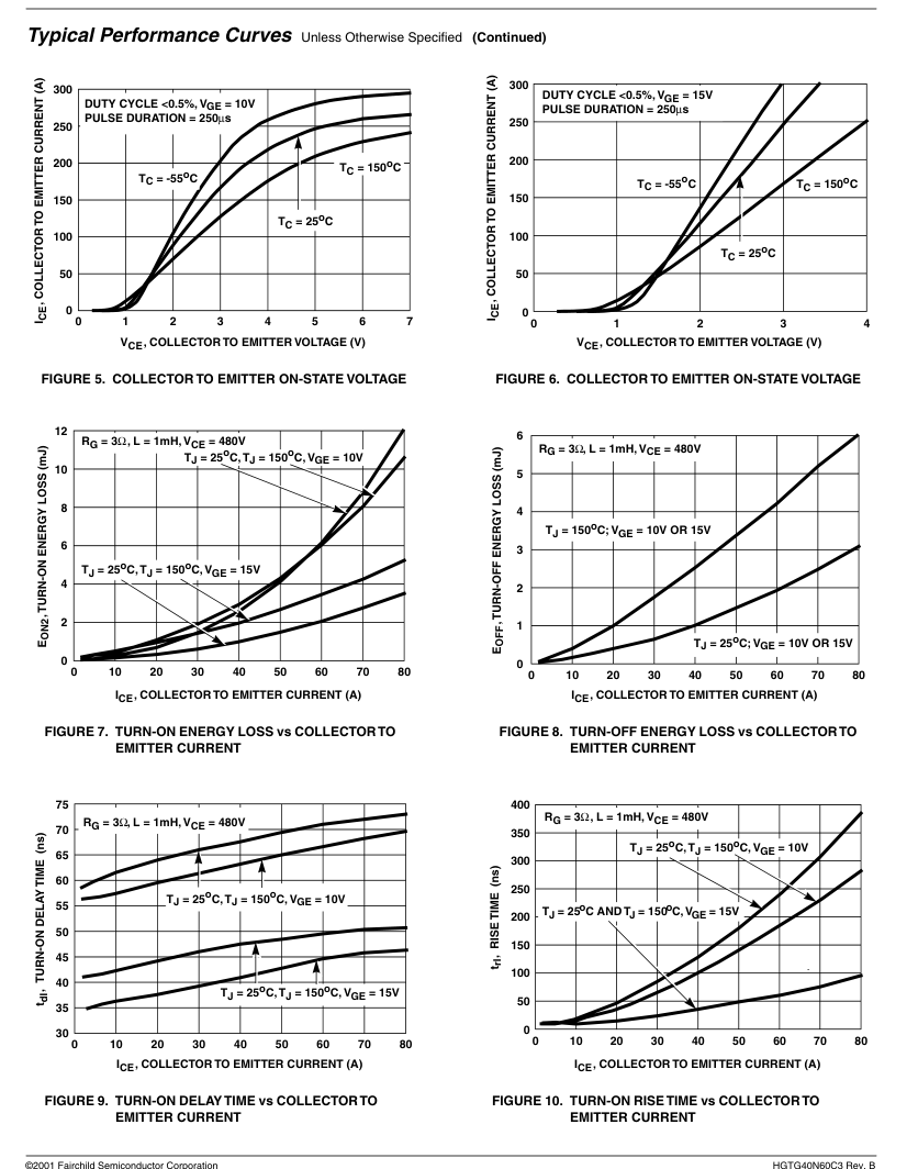
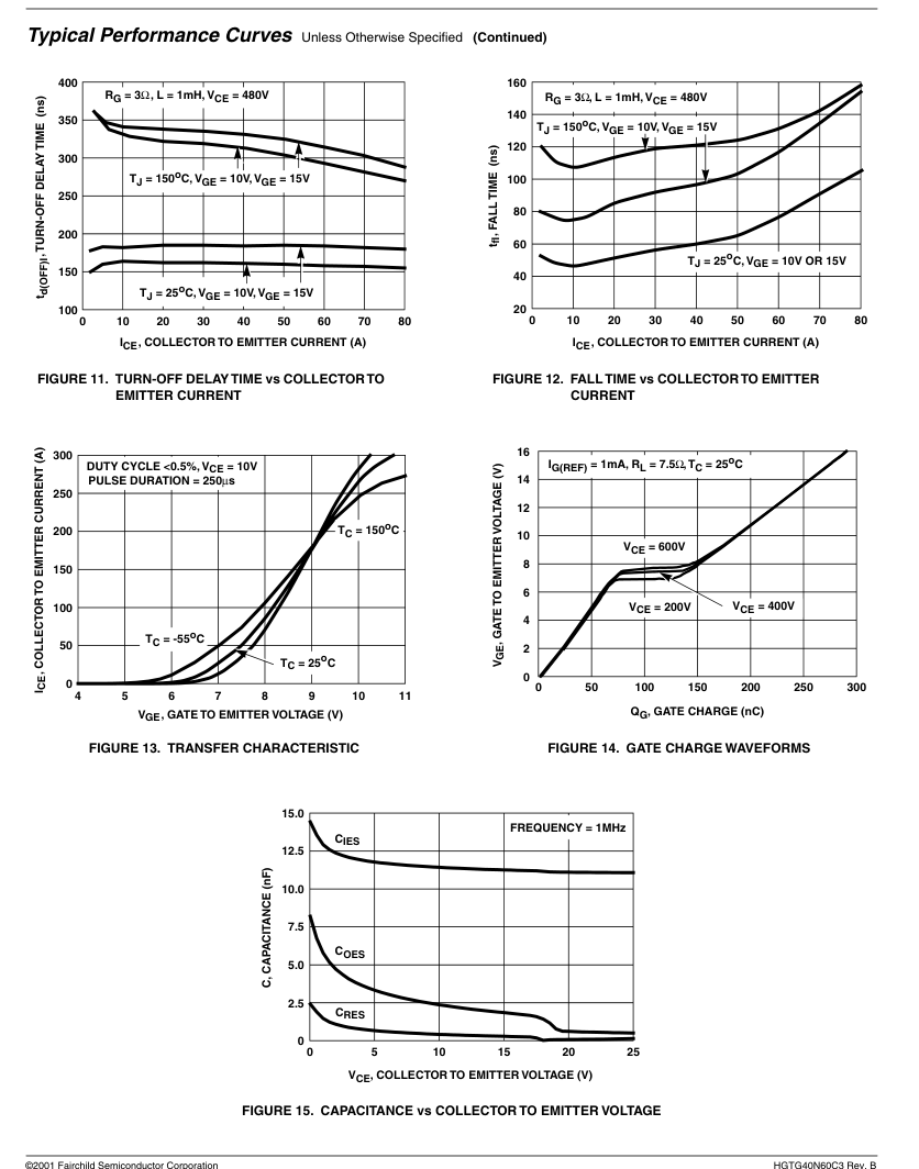
Operating frequency information for a typical device (Figure 3) is presented as a guide for estimating device performance for a specific application. Other typical frequency vs collector current (ICE) plots are possible using the information shown for a typical unit in Figures 5, 6, 7, 8, 9 and 11. The operating frequency plot (Figure 3) of a typical device shows fMAX1 or fMAX2; whichever is smaller at each point. The information is based on measurements of a typical device and is bounded by the maximum rated junction temperature.
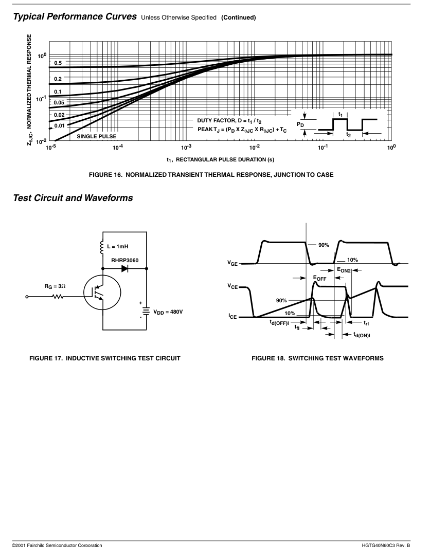
fMAX1 is defined by fMAX1 = 0.05/(td(OFF)I+ td(ON)I). Deadtime (the denominator) has been arbitrarily held to 10% of the on-state time for a 50% duty factor. Other definitions are possible. td(OFF)I and td(ON)I are defined in Figure 18. Device turn-off delay can establish an additional frequency limiting condition for an application other than TJM. td(OFF)I is important when controlling output ripple under a lightly loaded condition.
fMAX2 is defined by fMAX2 = (PD - PC)/(EOFF + EON2). The allowable dissipation (PD) is defined by PD = (TJM- TC)/RθJC. The sum of device switching and conduction losses must not exceed PD. A 50% duty factor was used (Figure 3) and the conduction losses (PC) are approximated by PC = (VCE x ICE)/2.
EON2 and EOFF are defined in the switching waveforms shown in Figure 18. EON2 is the integral of the instantaneous power loss (ICE x VCE) during turn-on and EOFF is the integral of the instantaneous power loss (ICE x VCE) during turn-off. All tail losses are included in the calculation for EOFF; i.e., the collector current equals zero (ICE = 0).
Page 8
TRADEMARKS
The following are registered and unregistered trademarks Fairchild Semiconductor owns or is authorized to use and is not intended to be an exhaustive list of all such trademarks.
FAST
ACEx™
FASTr™
Bottomless™
FRFET™
CoolFET™
GlobalOptoisolator™ POP™
CROSSVOLT™
GTO™
DenseTrench™
HiSeC™
DOME™
ISOPLANAR™
EcoSPARK™
LittleFET™
E2CMOSTM
QS™
MicroFET™
EnSignaTM
MicroPak™
FACT™
FACT Quiet Series™ MICROWIRE™
STAR\*POWER is used under license
DISCLAIMER
SMART START™ VCX™
OPTOLOGIC™
STAR\*POWER™
OPTOPLANAR™
Stealth™
PACMAN™
SuperSOT™-3
SuperSOT™-6
Power247™
SuperSOT™-8
PowerTrench
SyncFET™
QFET™
TinyLogic™
TruTranslation™
QT Optoelectronics™
UHC™
Quiet Series™
UltraFET
SILENT SWITCHER
FAIRCHILD SEMICONDUCTOR RESERVES THE RIGHT TO MAKE CHANGES WITHOUT FURTHER NOTICE TO ANY PRODUCTS HEREIN TO IMPROVE RELIABILITY, FUNCTION OR DESIGN. FAIRCHILD DOES NOT ASSUME ANY LIABILITY ARISING OUT OF THE APPLICATION OR USE OF ANY PRODUCT OR CIRCUIT DESCRIBED HEREIN; NEITHER DOES IT CONVEY ANY LICENSE UNDER ITS PATENT RIGHTS, NOR THE RIGHTS OF OTHERS.
LIFE SUPPORT POLICY
FAIRCHILD’S PRODUCTS ARE NOT AUTHORIZED FOR USE AS CRITICAL COMPONENTS IN LIFE SUPPORT DEVICES OR SYSTEMS WITHOUT THE EXPRESS WRITTEN APPROVAL OF FAIRCHILD SEMICONDUCTOR CORPORATION. As used herein: 1. Life support devices or systems are devices or systems which, (a) are intended for surgical implant into the body, or (b) support or sustain life, or (c) whose failure to perform when properly used in accordance with instructions for use provided in the labeling, can be reasonably expected to result in significant injury to the user.
PRODUCT STATUS DEFINITIONS
Definition of Terms
Datasheet Identification
Product Status
Advance Information
Formative or In Design
Preliminary
First Production
No Identification Needed
Full Production
Obsolete
Not In Production
- A critical component is any component of a life support device or system whose failure to perform can be reasonably expected to cause the failure of the life support device or system, or to affect its safety or effectiveness.
Definition
This datasheet contains the design specifications for product development. Specifications may change in any manner without notice.
This datasheet contains preliminary data, and supplementary data will be published at a later date. Fairchild Semiconductor reserves the right to make changes at any time without notice in order to improve design.
This datasheet contains final specifications. Fairchild Semiconductor reserves the right to make changes at any time without notice in order to improve design.
This datasheet contains specifications on a product that has been discontinued by Fairchild semiconductor. The datasheet is printed for reference information only.
Rev. H4