


 Download PDF
HGTP14N36G3VL FAIRCHILD
Document overview
- PDF pages: 8
Technical content
Page 1
HGTP14N36G3VL,
HGT1S14N36G3VL,
HGT1S14N36G3VLS
14A, 360V N-Channel,
Logic Level, Voltage Clamping IGBTs
December 2001
Features
Packages
- Logic Level Gate Drive
- Internal Voltage Clamp
- ESD Gate Protection
COLLECTOR
(FLANGE)
- TJ = 175oC
- Ignition Energy Capable
Description
This N-Channel IGBT is a MOS gated, logic level device which is intended to be used as an ignition coil driver in auto-
(FLANGE)
motive ignition circuits. Unique features include an active voltage clamp between the collector and the gate which provides Self Clamped Inductive Switching (SCIS) capability in ignition circuits. Internal diodes provide ESD protection for the logic level gate. Both a series resistor and a shunt resister are provided in the gate circuit.
PACKAGING AVAILABILITY
| PART NUMBER | PACKAGE | BRAND |
|---|---|---|
| HGTP14N36G3VL | TO-220AB | 14N36GVL |
| HGT1S14N36G3VL | TO-262AA | 14N36GVL |
| HGT1S14N36G3VLS | TO-263AB | 14N36GVL |
JEDEC TO-220AB
EMITTER
COLLECTOR
GATE
JEDEC TO-262AA
EMITTER
COLLECTOR
GATE
COLLECTOR
JEDEC TO-263AB
COLLECTOR
(FLANGE)
GATE
EMITTER
Terminal Diagram
NOTE: When ordering, use the entire part number. Add the suffix 9A to obtain the TO-263AB variant in the tape and reel, i.e., HGT1S14N36G3VLS9A. The development type number for this device is TA49021.
Absolute Maximum Ratings TC = +25oC, Unless Otherwise Specified
Collector-Emitter Bkdn Voltage at 10mA . . . . . . . . . . . . . . . . . . . . . . . . . . . . . . . . BVCER Emitter-Collector Bkdn Voltage at 10mA . . . . . . . . . . . . . . . . . . . . . . . . . . . . . . . . BVECS Collector Current Continuous at VGE = 5V, TC = +25oC. . . . . . . . . . . . . . . . . . . . . . . IC25
at VGE = 5V, TC = +100oC . . . . . . . . . . . . . . . . . . . . . . IC100
Gate-Emitter Voltage (Note) . . . . . . . . . . . . . . . . . . . . . . . . . . . . . . . . . . . . . . . . . . . VGEM Inductive Switching Current at L = 2.3mH, TC = +25oC . . . . . . . . . . . . . . . . . . . . . . . ISCIS
at L = 2.3mH, TC = + 175oC . . . . . . . . . . . . . . . . . . . . . . ISCIS
Collector to Emitter Avalanche Energy at L = 2.3mH, TC = +25oC. . . . . . . . . . . . . . . EAS Power Dissipation Total at TC = +25oC . . . . . . . . . . . . . . . . . . . . . . . . . . . . . . . . . . . . PD Power Dissipation Derating TC > +25oC. . . . . . . . . . . . . . . . . . . . . . . . . . . . . . . . . . . . . . . Operating and Storage Junction Temperature Range . . . . . . . . . . . . . . . . . . . . . TJ, TSTG Maximum Lead Temperature for Soldering . . . . . . . . . . . . . . . . . . . . . . . . . . . . . . . . . . TL Electrostatic Voltage at 100pF, 1500Ω. . . . . . . . . . . . . . . . . . . . . . . . . . . . . . . . . . . . ESD
NOTE: May be exceeded if IGEM is limited to 10mA.
N-CHANNEL ENHANCEMENT MODE
COLLECTOR
R1
GATE
R2
EMITTER
HGTP14N36G3VL,
HGT1S14N36G3VL,
HGT1S14N36G3VLS
UNITS
390
V
24
V
18
A
14
A
±10
V
17
A
12
A
332
mJ
100
W W/oC
0.67
oC
-40 to +175
oC KV
Page 2
Specifications HGTP14N36G3VL, HGT1S14N36G3VL, HGT1S14N36G3VLS
Electrical Specifications TC = +25oC, Unless Otherwise Specified
| PARAMETERS | SYMBOL | TEST CONDITIONS | LIMITS | UNITS | |||
|---|---|---|---|---|---|---|---|
| MIN | TYP | MAX | |||||
| Collector-Emitter Breakdown Voltage | BV CER | I = 10mA, C V = 0V GE R = 1kΩ GE | T = +175oC C | 320 | 355 | 400 | V |
| T = +25oC C | 330 | 360 | 390 | V | |||
| T = -40oC C | 320 | 350 | 385 | V | |||
| Gate-Emitter Plateau Voltage | V GEP | I = 7A, C V = 12V CE | T = +25oC C | - | 2.7 | - | V |
| Gate Charge | Q G(ON) | I = 7A, C V = 12V CE | T = +25oC C | - | 24 | - | nC |
| Collector-Emitter Clamp Breakdown Voltage | BV CE(CL) | I = 7A C R = 1000Ω G | T = +175oC C | 350 | 380 | 410 | V |
| Emitter-Collector Breakdown Voltage | BV ECS | I = 10mA C | T = +25oC C | 24 | 28 | - | V |
| Collector-Emitter Leakage Current | I CER | V = 250V CE R = 1kΩ GE | T = +25oC C | - | - | 25 | µA |
| T = +175oC C | - | - | 250 | µA | |||
| Collector-Emitter Saturation Voltage | V CE(SAT) | I = 7A C V = 4.5V GE | T = +25oC C | - | 1.25 | 1.45 | V |
| T = +175oC C | - | 1.15 | 1.6 | V | |||
| I = 14A C V = 5V GE | T = +25oC C | - | 1.6 | 2.2 | V | ||
| T = +175oC C | - | 1.7 | 2.9 | V | |||
| Gate-Emitter Threshold Voltage | V GE(TH) | I = 1mA C V = V CE GE | T = +25oC C | 1.3 | 1.8 | 2.2 | V |
| Gate Series Resistance | R 1 | T = +25oC C | - | 75 | - | Ω | |
| Gate-Emitter Resistance | R 2 | T = +25oC C | 10 | 20 | 30 | kΩ | |
| Gate-Emitter Leakage Current | I GES | V = ±10V GE | ±330 | ±500 | ±1000 | µA | |
| Gate-Emitter Breakdown Voltage | BV GES | I = ±2mA GES | ±12 | ±14 | - | V | |
| Current Turn-Off Time-Inductive Load | t + D(OFF)I t F(OFF)I | I = 7A, R = 28Ω C L R = 25Ω, L = 550µH, G V = 300V, V = 5V, CL GE T = +175oC C | - | 7 | - | µs | |
| Inductive Use Test | I SCIS | L = 2.3mH, V = 5V, G | T = +175oC C | 12 | - | - | A |
| T = +25oC C | 17 | - | - | A | |||
| Thermal Resistance | R θJC | - | - | 1.5 | oC/W | ||
Page 3
Page 4
Page 5
Page 6
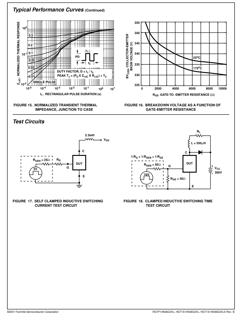
Page 7
Handling Precautions for IGBT’s
Insulated Gate Bipolar Transistors are susceptible to gateinsulation damage by the electrostatic discharge of energy through the devices. When handling these devices, care should be exercised to assure that the static charge built in the handler’s body capacitance is not discharged through the device. With proper handling and application procedures, however, IGBT’s are currently being extensively used in production by numerous equipment manufacturers in military, industrial and consumer applications, with virtually no damage problems due to electrostatic discharge. IGBT’s can be handled safely if the following basic precautions are taken: 1. Prior to assembly into a circuit, all leads should be kept
.
shorted together either by the use of metal shorting springs or by the insertion into conductive material such as †“ECCOSORBD LD26” or equivalent. 2. When devices are removed by hand from their carriers, the hand being used should be grounded by any suitable means - for example, with a metallic wristband. 3. Tips of soldering irons should be grounded. 4. Devices should never be inserted into or removed from circuits with power on. 5. Gate Voltage Rating -The gate-voltage rating of VGEM may be exceeded if IGEM is limited to 10mA. † Trademark Emerson and Cumming, Inc
FAIRCHILD CORPORATION IGBT PRODUCT IS COVERED BY ONE OR MORE OF THE FOLLOWING U.S. PATENTS:
4,364,073
4,417,385
4,430,792
4,443,931
4,466,176
4,516,143
4,532,534
4,567,641
4,587,713
4,598,461
4,605,948
4,618,872
4,620,211
4,631,564
4,639,754
4,639,762
4,641,162
4,644,637
4,682,195
4,684,413
4,694,313
4,717,679
4,743,952
4,783,690
4,794,432
4,801,986
4,803,533
4,809,045
4,809,047
4,810,665
4,823,176
4,837,606
4,860,080
4,883,767
4,888,627
4,890,143
4,901,127
4,904,609
4,933,740
4,963,951
4,969,027
Page 8
TRADEMARKS
The following are registered and unregistered trademarks Fairchild Semiconductor owns or is authorized to use and is not intended to be an exhaustive list of all such trademarks.
FAST
ACEx™
FASTr™
Bottomless™
FRFET™
CoolFET™
GlobalOptoisolator™ POP™
CROSSVOLT™
GTO™
DenseTrench™
HiSeC™
DOME™
ISOPLANAR™
EcoSPARK™
LittleFET™
E2CMOSTM
QS™
MicroFET™
EnSignaTM
MicroPak™
FACT™
FACT Quiet Series™ MICROWIRE™
STAR\*POWER is used under license
DISCLAIMER
SMART START™ VCX™
OPTOLOGIC™
STAR\*POWER™
OPTOPLANAR™
Stealth™
PACMAN™
SuperSOT™-3
SuperSOT™-6
Power247™
SuperSOT™-8
PowerTrench
SyncFET™
QFET™
TinyLogic™
TruTranslation™
QT Optoelectronics™
UHC™
Quiet Series™
UltraFET
SILENT SWITCHER
FAIRCHILD SEMICONDUCTOR RESERVES THE RIGHT TO MAKE CHANGES WITHOUT FURTHER NOTICE TO ANY PRODUCTS HEREIN TO IMPROVE RELIABILITY, FUNCTION OR DESIGN. FAIRCHILD DOES NOT ASSUME ANY LIABILITY ARISING OUT OF THE APPLICATION OR USE OF ANY PRODUCT OR CIRCUIT DESCRIBED HEREIN; NEITHER DOES IT CONVEY ANY LICENSE UNDER ITS PATENT RIGHTS, NOR THE RIGHTS OF OTHERS.
LIFE SUPPORT POLICY
FAIRCHILD’S PRODUCTS ARE NOT AUTHORIZED FOR USE AS CRITICAL COMPONENTS IN LIFE SUPPORT DEVICES OR SYSTEMS WITHOUT THE EXPRESS WRITTEN APPROVAL OF FAIRCHILD SEMICONDUCTOR CORPORATION. As used herein: 1. Life support devices or systems are devices or systems which, (a) are intended for surgical implant into the body, or (b) support or sustain life, or (c) whose failure to perform when properly used in accordance with instructions for use provided in the labeling, can be reasonably expected to result in significant injury to the user.
PRODUCT STATUS DEFINITIONS
Definition of Terms
Datasheet Identification
Product Status
Advance Information
Formative or In Design
Preliminary
First Production
No Identification Needed
Full Production
Obsolete
Not In Production
- A critical component is any component of a life support device or system whose failure to perform can be reasonably expected to cause the failure of the life support device or system, or to affect its safety or effectiveness.
Definition
This datasheet contains the design specifications for product development. Specifications may change in any manner without notice.
This datasheet contains preliminary data, and supplementary data will be published at a later date. Fairchild Semiconductor reserves the right to make changes at any time without notice in order to improve design.
This datasheet contains final specifications. Fairchild Semiconductor reserves the right to make changes at any time without notice in order to improve design.
This datasheet contains specifications on a product that has been discontinued by Fairchild semiconductor. The datasheet is printed for reference information only.
Rev. H4