


 Download PDF
HFA16TA60CS IRF
Document overview
- PDF pages: 6
Technical content
Page 1
Bulletin PD -20373 01/01
HFA16TA60CS
Ultrafast, Soft Recovery Diode
HEXFRED
TM
Features
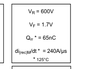
- Ultrafast Recovery
- Ultrasoft Recovery
- Very Low IRRM
- Very Low Qrr
- Specified at Operating Conditions
Benefits
- Reduced RFI and EMI
- Reduced Power Loss in Diode and Switching
Transistor
- Higher Frequency Operation
- Reduced Snubbing
- Reduced Parts Count
Description
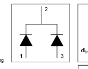
International Rectifier's HFA16TA60CS is a state of the art center tap ultra fast recovery diode. Employing the latest in epitaxial construction and advanced processing techniques it features a superb combination of characteristics which result in performance which is unsurpassed by any rectifier previously available. With basic ratings of 600 volts and 8 amps per Leg continuous current, the HFA16TA60CS is especially well suited for use as the companion diode for IGBTs and MOSFETs. In addition to ultra fast recovery time, the HEXFRED product line features extremely low values of peak recovery current (IRRM) and does not exhibit any tendency to "snap-off" during the tb portion of
recovery. The HEXFRED features combine to offer designers a rectifier with lower noise and significantly lower switching losses in both the diode and the switching transistor. These HEXFRED advantages can help to significantly reduce snubbing, component count and heatsink sizes. The HEXFRED HFA16TA60CS is ideally suited for applications in power supplies and power conversion systems (such as inverters), motor drives, and many other similar applications where high speed, high efficiency is needed.
Absolute Maximum Ratings (per Leg)
| Parameter | Max | Units | |
|---|---|---|---|
| VR | Cathode-to-Anode Voltage | 600 | V |
| IF @ TC = 100°C | Continuous Forward Current | 8.0 | A |
| IFSM | Single Pulse Forward Current | 60 | |
| IFRM | Maximum Repetitive Forward Current | 24 | |
| PD @ TC = 25°C | Maximum Power Dissipation | 36 | W |
| PD @ TC = 100°C | Maximum Power Dissipation | 14 | |
| TJ | Operating Junction and | - 55 to +150 | °C |
| TSTG | Storage Temperature Range |
1
Page 2
HFA16TA60CS
Bulletin PD-20373 01/01
Electrical Characteristics (per Leg) @ TJ = 25°C (unless otherwise specified)
| Parameter | Min | Typ | Max | Units | Test Conditions | |
|---|---|---|---|---|---|---|
| VBR | Cathode Anode Breakdown Voltage | 600 | V | IR = 100µA | ||
| VFM | Max Forward Voltage | 1.4 | 1.7 | V | IF = 8A See Fig. 1 IF = 16A IF = 8A, TJ = 125°C | |
| 1.7 | 2.1 | |||||
| 1.4 | 1.7 | |||||
| IRM | Max Reverse Leakage Current | 0.3 | 5 | µA | VR = VR Rated See Fig. 2 TJ = 125°C, VR = 0.8 x VR Rated D Rated | |
| 100 | 500 | |||||
| CT | Junction Capacitance | 10 | 25 | pF | VR = 200V See Fig. 3 | |
| LS | Series Inductance | 8.0 | nH | Measured lead to lead 5mm from package body |
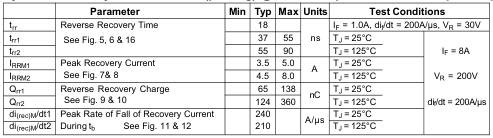
Dynamic Recovery Characteristics (per Leg) @ TJ = 25°C (unless otherwise specified)
Thermal - Mechanical Characteristics
| Parameter | Min | Typ | Max | Units | |
|---|---|---|---|---|---|
| Tlead! | Lead Temperature | 300 | °C | ||
| RthJC | Junction-to-Case, Single Leg Conducting Junction-to-Case, Both Legs Conducting | 3.5 | K/W | ||
| 1.75 | |||||
| RthJA" | Thermal Resistance, Junction to Ambient | 80 | |||
| Wt | Weight | 2 | g | ||
| 0.07 | (oz) | ||||
| Mounting Torque | 6 | 12 | Kg-cm | ||
| 5 | 10 | lbf•in |
! 0.063 in. from Case (1.6mm) for 10 sec " Typical Socket Mount
2
www.irf.com
Page 3
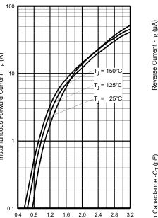
Forward Voltage Drop - V (V)
FM
Fig. 1 - Maximum Forward Voltage Drop vs. Instantaneous Forward Current, (per Leg)
HFA16TA60CS
Bulletin PD-20373 01/01
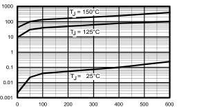
Reverse Voltage - V (V)
R
Fig. 2 - Typical Reverse Current vs. Reverse Voltage, (per Leg)
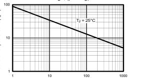
Reverse Voltage - VR ( V ) Reverse Voltage - V (V)
R
Fig. 3 - Typical Junction Capacitance vs.
Page 4
HFA16TA60CS
Bulletin PD-20373 01/01
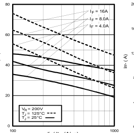
di /dt - (A/µs) f
Fig. 5 - Typical Reverse Recovery vs. dif/dt,
(per Leg)
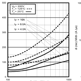
di /dt - (A/µs) f
Fig. 7 - Typical Stored Charge vs. dif/dt,
(per Leg)
4
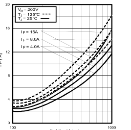
di /dt - (A/µs) f
Fig. 6 - Typical Recovery Current vs. dif/dt,
(per Leg)
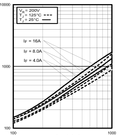
di /dt - (A/µs) f
Fig. 8 - Typical di(rec)M/dt vs. dif/dt, (per Leg)
www.irf.com
Page 5
0
REVERSE RECOVERY CIRCUIT
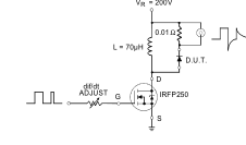
Fig. 9 - Reverse Recovery Parameter Test
Circuit
www.irf.com
HFA16TA60CS
Bulletin PD-20373 01/01
| F | 3 trr ta tb | |
| Qrr4 2 I RRM 0.5I RRM di(rec)M/dt 5 0.75 IRRM | ||
di /dt f
- Qrr - Area under curve defined by trr
- dif/dt - Rate of change of current
and IRRM
through zero crossing
trr X IRRM Qrr =
- IRRM - Peak reverse recovery current
2
- trr - Reverse recovery time measured
- di(rec)M/dt - Peak rate of change of
from zero crossing point of negative
current during tb portion of trr
going IF to point where a line passing through 0.75 IRRM and 0.50 IRRM extrapolated to zero current
Fig. 10 - Reverse Recovery Waveform and
Definitions
5
Page 6
HFA16TA60CS
Bulletin PD-20373 01/01
IR WORLD HEADQUARTERS: 233 Kansas St., El Segundo, California 90245, USA Tel: (310) 252-7105
TAC Fax: (310) 252-7309
Visit us at www.irf.com for sales contact information. 01/01
6