


 Download PDF
HFA08SD60SPBF VISHAY
Document overview
- PDF pages: 7
Technical content
Page 1
FEATURES
- Ultrafast recovery time
- Ultrasoft recovery
Available
RoHS\*
- Very low IRRM
COMPLIANT
- Very low Qrr
- Guaranteed avalanche
- Specified at operating conditions
- Lead (Pb)-free
- Designed and qualified for Q101 level
BENEFITS
- Reduced RFI and EMI
- Reduced power loss in diode and switching transistor
- Higher frequency operation
| PRODUCT SUMMARY | |
| V R | 600 V |
| V at 8 A at 25 °C F | 1.7 V |
| I F(AV) | 8 A |
| t (typical) rr | 18 ns |
| T (maximum) J | 150 °C |
- Reduced snubbing
- Reduced parts count
DESCRIPTION
These diodes are optimized to reduce losses and EMI/RFI in high frequency power conditioning systems. The softness of the recovery eliminates the need for a snubber in most applications. These devices are ideally suited for freewheeling, flyback, power converters, motor drives, and other applications where high speed and reduced switching losses are design requirements.
| ABSOLUTE MAXIMUM RATINGS | ||||
|---|---|---|---|---|
| PARAMETER | SYMBOL | TEST CONDITIONS | VALUES | UNITS |
| Cathode to anode voltage | V RRM | 600 | V | |
| Maximum continuous forward current | I F | T = 100 °C C | 8 | A |
| Single pulse forward current | I FSM | 60 | ||
| Peak repetitive forward current | I FRM | 24 | ||
| Maximum power dissipation | P D | T = 100 °C C | 14 | W |
| Operating junction and storage temperature range | T , T J Stg | - 55 to + 150 | °C | |
| ELECTRICAL SPECIFICATIONS (T = 25 °C unless otherwise specified) J | |||||||
| PARAMETER | SYMBOL | TEST CONDITIONS | MIN. | TYP. | MAX. | UNITS | |
| Breakdown voltage, blocking voltage | V , BR V R | I = 100 µA R | 600 | - | - | V | |
| Forward voltage | V F | I = 8 A F | See fig. 1 | - | 1.4 | 1.7 | |
| I = 16 A F | - | 1.7 | 2.1 | ||||
| I = 8 A, T = 125 °C F J | - | 1.4 | 1.7 | ||||
| Maximum reverse leakage current | I R | V = V rated R R | - | 0.3 | 5.0 | µA | |
| T = 125 °C, V = 0.8 x V rated J R R | - | 100 | 500 | ||||
| Junction capacitance | C T | V = 200 V R | See fig. 3 | - | 10 | 25 | pF |
| Series inductance | L S | Measured lead to lead 5 mm from package body | - | 8.0 | - | nH | |
\* Pb containing terminations are not RoHS compliant, exemptions may apply
Page 2
| DYNAMIC RECOVERY CHARACTERISTICS (T = 25 °C unless otherwise specified) J | |||||||
| PARAMETER | SYMBOL | TEST CONDITIONS | MIN. | TYP. | MAX. | UNITS | |
| Reverse recovery time | t rr | I = 1.0 A, dI /dt = 200 A/µs, V = 30 V F F R | - | 18 | - | ns | |
| T = 25 °C J | I = 8 A F dI /dt = 200 A/µs F V = 200 V R | - | 37 | 55 | |||
| T = 125 °C J | - | 55 | 90 | ||||
| Peak recovery current | I RRM | T = 25 °C J | - | 3.5 | 5.0 | A | |
| T = 125 °C J | - | 4.5 | 8.0 | ||||
| Reverse recovery charge | Q rr | T = 25 °C J | - | 65 | 138 | nC | |
| T = 125 °C J | - | 124 | 360 | ||||
| Rate of fall of recovery current | dI /dt (rec)M | T = 25 °C J | - | 240 | - | A/µs | |
| T = 125 °C J | - | 210 | - | ||||
| THERMAL - MECHANICAL SPECIFICATIONS | ||||||
| PARAMETER | SYMBOL | TEST CONDITIONS | MIN. | TYP. | MAX. | UNITS |
| Maximum junction and storage temperature range | T, T J Stg | - 55 | - | 150 | °C | |
| Lead temperature | T lead | - | - | 300 | ||
| Thermal resistance, junction to case | R thJC | - | - | 3.5 | °C/W | |
| Thermal resistance, junction to ambient | R thJA | Typical socket mount | - | - | 80 | |
| Weight | - | 2.0 | - | g | ||
| - | 0.07 | - | oz. | |||
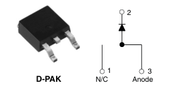
| Marking device | Case style D-PAK | HFA08SD60S | ||||
Page 3
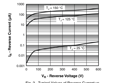
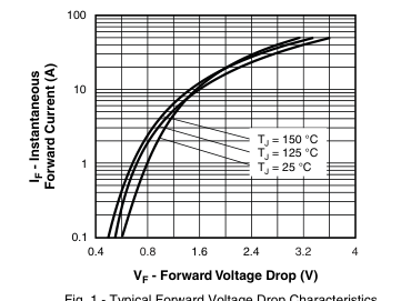
Fig. 1 - Typical Forward Voltage Drop Characteristics
Fig. 2 - Typical Values of Reverse Current vs.
Reverse Voltage
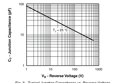
Fig. 3 - Typical Junction Capacitance vs. Reverse Voltage
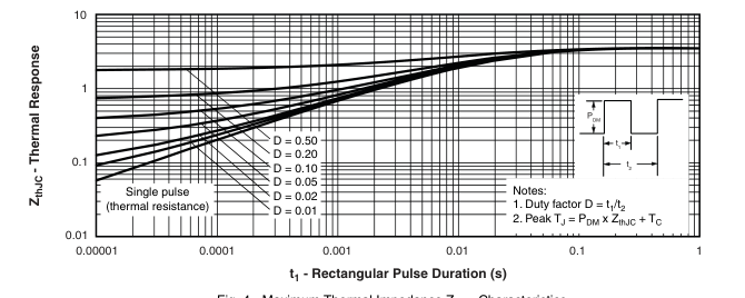
Fig. 4 - Maximum Thermal Impedance ZthJC Characteristics
Page 4
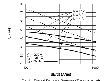
Fig. 5 - Typical Reverse Recovery Time vs. dIF/dt
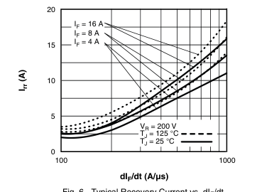
Fig. 6 - Typical Recovery Current vs. dIF/dt
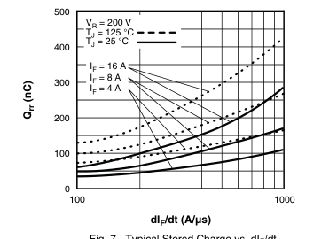
Fig. 7 - Typical Stored Charge vs. dIF/dt
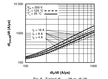
Fig. 8 - Typical dI(rec)M/dt vs. dIF/dt
Page 5
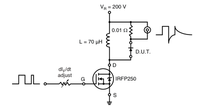
Fig. 9 - Reverse Recovery Parameter Test Circuit
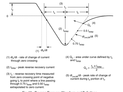
Fig. 10 - Reverse Recovery Waveform and Definitions
Page 6
ORDERING INFORMATION TABLE
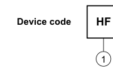
| HF | A | 08 | SD | 60 | S | PbF |
| 1 2 3 4 5 6 7 | ||||||

| e rating (60 = 600 V) | S = D2PAK/D-PAK TR = Tape and reel TRL = Tape and reel left TRR = Tape and reel right |
| = Standard production |
PbF = Lead (Pb)-free
| LINKS TO RELATED DOCUMENTS | |
| Dimensions | http://www.vishay.com/doc?95016 |
| Part marking information | http://www.vishay.com/doc?95059 |
| Packaging information | http://www.vishay.com/doc?95033 |
Page 7
Legal Disclaimer Notice
Vishay
Disclaimer
All product specifications and data are subject to change without notice.
Vishay Intertechnology, Inc., its affiliates, agents, and employees, and all persons acting on its or their behalf (collectively, “Vishay”), disclaim any and all liability for any errors, inaccuracies or incompleteness contained herein or in any other disclosure relating to any product.
Vishay disclaims any and all liability arising out of the use or application of any product described herein or of any information provided herein to the maximum extent permitted by law. The product specifications do not expand or otherwise modify Vishay’s terms and conditions of purchase, including but not limited to the warranty expressed therein, which apply to these products.
No license, express or implied, by estoppel or otherwise, to any intellectual property rights is granted by this document or by any conduct of Vishay.
The products shown herein are not designed for use in medical, life-saving, or life-sustaining applications unless otherwise expressly indicated. Customers using or selling Vishay products not expressly indicated for use in such applications do so entirely at their own risk and agree to fully indemnify Vishay for any damages arising or resulting from such use or sale. Please contact authorized Vishay personnel to obtain written terms and conditions regarding products designed for such applications.
Product names and markings noted herein may be trademarks of their respective owners.
Document Number: 91000 Revision: 18-Jul-08