
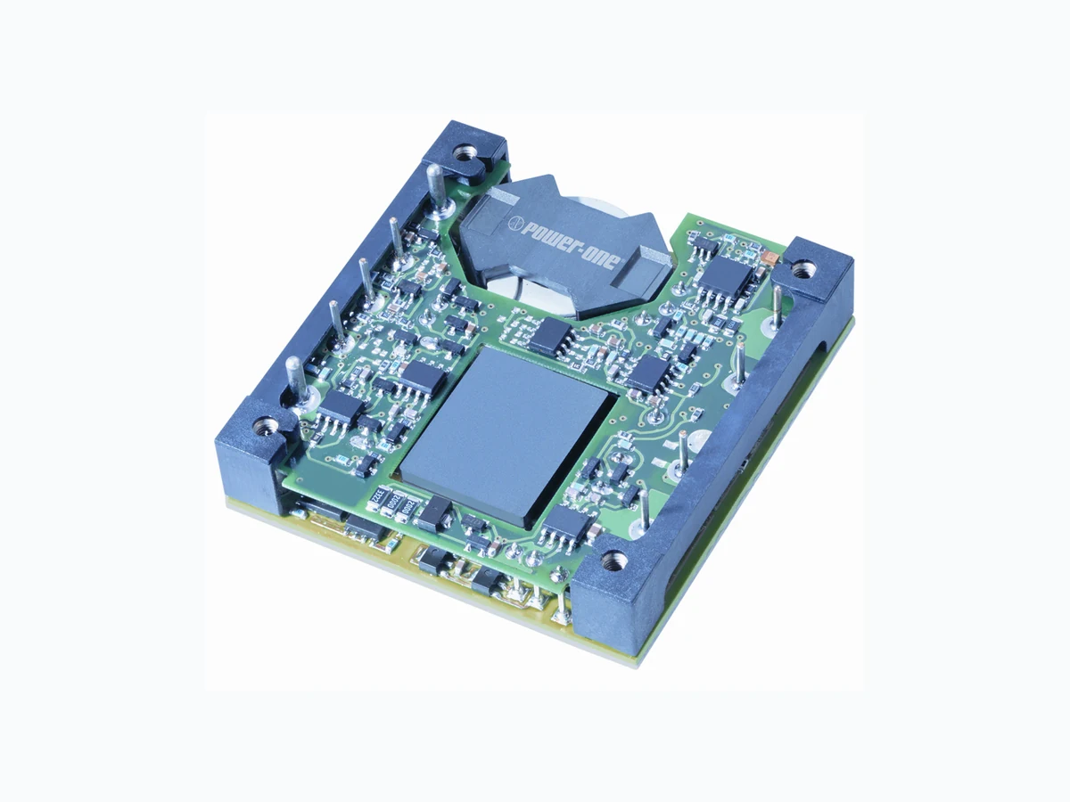
HBC25ZH-NT POWER-ONE
Document overview
- Manufacturer or author: Provided By www.digicamel.com(FREE DATASHEET DOWNLOAD SITE)
- PDF pages: 7
Technical content
Features
- High efficiency up to 94%
- High power density – 110 W/in 3
- High current rating - 25A
- Low profile – 12.7mm height
- Input/output isolation: 1500VDC
- Basic insulation
- Start-up into high capacitive load
- Low conducted and radiated EMI
- Output overcurrent protection
- Output overvoltage protection
- Overtemperature protection
- Remote sense
- Remote on/off (primary referenced), positive or negative logic option
- Adjustable output voltage from 9.6V to 13.2V
- UL 1950 Recognition, CSA 22.2 No. 950-95 certification, TUV IEC950
Description
The HBC Series of high density bus converters convert a worldwide telecom bus voltage of 36 to 75VDC to a 12V bus at 25A. The output is ideal for powering non-isolated, point-of-load converters such as synchronous buck converters used commonly in intermediate bus architectures. The unit's open-frame, two-board construction provides ideal thermal transfer for maximum reliability. Power devices are mounted on an Insulated Metal Substrate (IMS) base plate with very low thermal impedance. The control PCB is physically isolated from the hotter IMS board, providing lower overall component temperatures for high reliability. The standard feature set includes remote on/off, remote output voltage sensing, positive output trim, input undervoltage lockout, and overtemperature shutdown with hysteresis. Model Selection Model Input Voltage VDC Input Current, Max ADC Output Voltage Vout, VDC Output rated Current I rated, ADC Output Ripple/Noise, mV p-p Typical Efficiency @ I rated, % HBC25ZH 36-75 10 12.0 25 150 92
REV. DEC 15, 2003 www.power-one.com Page 2 of 7 HBC DC-DC Series Data Sheet 300-Watt Half-Brick Converters Absolute Maximum Ratings Stresses in excess of the absolute maximum ratings may cause performance degradation, adversely effect long- term reliability, and cause permanent damage to the converter. Parameter Conditions/Description Min Max Units Input voltage Continuous Transient, 100ms 100 VDC VDC Operating Temperature Base Plate Temperature -40 110 °C Storage Temperature -55 125 °C ON/OFF Control Voltage Referenced to -Vin 7 VDC Environmental and Mechanical Specifications All specifications apply over specified input voltage, output load, and temperature range, unless otherwise noted. Parameter Conditions/Description Min Nom Max Units Shock Halfsine wave, 3 axes 50 g Sinusoidal Vibration GR-63-CORE, Section 5.4.2 1 g Weight 2.6/73 gm Water Washing Standard process Yes MTBF Per Bellcore TR-NWT-000332 1,100 kHrs Isolation Specifications All specifications apply over specified input voltage, output load and temperature range, unless otherwise noted. Parameter Conditions/Description Min Nom Max Units Insulation Safety Rating Basic Isolation Voltage Input to output, output to base plate 1500 VDC Isolation Voltage Input to base plate 1500 VDC Isolation Resistance 10 MOhm Isolation Capacitance 1000 pF Input Specifications All specifications apply over specified input voltage, output load and temperature range, unless otherwise noted. Parameter Conditions/Description Min Nom Max Units Input Voltage Continuous 36 48 75 VDC Turn-On Input Voltage Ramping Up 33 36 VDC Turn-Off Input Voltage Ramping Down 31 33 VDC Turn-On Time for turn-on via application of input voltage Time from Vin=UVLO to regulation band 60 85 mS Turn-On Time for turn-on via ON/OFF signal Time from ON/OFF signal to regulation band 10 25 mS Input Reflected Ripple Current Full Load, 12µH source inductance 200 mA p-p Inrush Transient Vin=Vin.max 0.25 A 2s
REV. DEC 15, 2003 www.power-one.com Page 3 of 7 HBC DC-DC Series Data Sheet 300-Watt Half-Brick Converters Output Specifications All specifications apply over specified input voltage, output load, and temperature range, unless otherwise noted. Parameter Conditions/Description Min Nom Max Units Output Voltage Setpoint Accuracy Vin=Vin.nom, Full Load -2 2 %Vout Output Current* See selection chart for I rated 0 25 A Line Regulation Vin.min to Vin.max, I rated 0.5 %Vout Load Regulation Vin=Vin.nom, 10% to 100%I rated 1.0 %Vout Total output voltage regulation Over all input voltage, load, and temperature conditions -4 4 %Vout Remote Sense Headroom 5% %Vout Dynamic Regulation Peak Deviation Settling Time 75-100% load step change to 1% error band 600 600 1,000 mV µs Admissible Load Capacitance I rated, Nom Vin 15,000 µF Output Current Limit Threshold Vout ≤0.97Vout.nom 110 150 %I rated Switching Frequency 400 kHz Overvoltage Protection, Latching Over all input voltage and load conditions 115 125 %Vout Trim Range I rated, Vin=Vnom 80 110 %Vout Overcurrent protection is non-latching with auto recovery. Feature Specifications All specifications apply over specified input voltage, output load, and temperature range, unless otherwise noted. Parameter Conditions/Description Min Nom Max Units Shutdown (ON/OFF) Negative Logic Converter ON Source Current Converter OFF Open Circuit Voltage Positive Logic Converter ON Open Circuit Voltage Converter OFF Source Current On/Off signal is low – converter is ON ON/OFF pin is connected to -Vin ON/OFF pin is floating On/Off signal is low–converter is OFF ON/OFF pin is floating ON/OFF pin is connected to -Vin -0.5 2.5 2.5 -0.5 0.8 0.5 0.8 0.5 VDC MADC VDC VDC VDC VDC VDC mADC Overtemperature Protection Base Plate Temperature 120 130 °C
Figure 3. HBC Series Positive Trim Schematic required to achieve a ∆V change in the output voltage. percents of the nominal output voltage, Vo.
- When the output voltage is trimmed up, the output power from
and multiplying it by the output current.
- In order to avoid creating apparent load regulation degradation, it
- The output voltage increase can be accomplished by either the
circuits according to all IEC60950 based standards. The HBC Series converters have no internal fuse. not be placed in the grounded input line, if any.
- If the voltage source feeding the module is SELV or TNV-2, the output of the converter may be grounded or ungrounded.
- If the voltage source feeding the module is ELV, the output of the converter may be considered SELV only if the output is grounded per the requirements of the standard.
- If the voltage source feeding the module is a Hazardous Voltage Secondary Circuit, the voltage source feeding the module must be provided with at least basic insulation between the source to the converter and any hazardous voltages. The entire system, including the HBC converter, must pass a dielectric withstand test for reinforced insulation. Design of this type of systems requires expert engineering and under- standing of the overall safety requirements and should be performed by qualified personnel.
ensure reliable long-term operation of the converters. Figure 4. HBC25ZH-T, NT Derating Curves
REV. DEC 15, 2003 www.power-one.com Page 7 of 7 HBC DC-DC Series Data Sheet 300-Watt Half-Brick Converters Mechanical Drawing Mechanical Tolerances Inches Millimeters X.XX ±0.020 X.X ±0.5 X.XXX ±0.010 X. XX ±0.25 Pin ±0.002 ±0.05
Ordering Information
Options Suffixes to add to part number Positive- Standard, no suffix required Remote ON/OFF Negative- Add “N” suffix Trim Positive - “T” suffix (required - all models) 0.18”- Standard, no suffix required 0.145”- Add “7” suffix Pin Length 0.110”- Add “8” suffix Example: HBC25ZH-T8 is a positive on/off logic, industry standard Trim, 12V output converter with 0.110” pin length Notes 1. Consult factory for the complete list of available options. NUCLEAR AND MEDICAL APPLICATIONS - Power-One products are not authorized for use as critical components in life support systems , equipment used in hazardous environments, or nuclear control systems without the express written consent of the respective divi sional president of Power-One, Inc. TECHNICAL REVISIONS - The appearance of products, including safety agency certifications pictured on labels, may change depending on the date manufactured. Specifications are subject to change without notice. Pin Function 1 -Vin