


 Download PDF
GTL2010 10-bit bidirectional low voltage translator
Document overview
- PDF pages: 20
Technical content
Page 1
1. General description
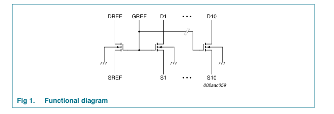
The Gunning Transceiver Logic - Transceiver Voltage Clamps (GTL-TVC) provide high-speed voltage translation with low ON-state resistance and minimal propagation delay. The GTL2010 provides 10 NMOS pass transistors (Sn and Dn) with a common gate (GREF) and a reference transistor (SREF and DREF). The device allows bidirectional voltage translations between 1.0 V and 5.0 V without use of a direction pin.
When the Sn or Dn port is LOW, the clamp is in the ON-state and a low resistance connection exists between the Sn and Dn ports. Assuming the higher voltage is on the Dn port, when the Dn port is HIGH the voltage on the Sn port is limited to the voltage set by the reference transistor (SREF). When the Sn port is HIGH, the Dn port is pulled to VCC by the pull-up resistors. This functionality allows a seamless translation between higher and lower voltages selected by the user, without the need for directional control.
All transistors have the same electrical characteristics and there is minimal deviation from one output to another in voltage or propagation delay. This is a benefit over discrete transistor voltage translation solutions, since the fabrication of the transistors is symmetrical. Because all transistors in the device are identical, SREF and DREF can be located on any of the other ten matched Sn/Dn transistors, allowing for easier board layout. The translator's transistors provide excellent ESD protection to lower voltage devices and at the same time protect less ESD-resistant devices.
2. Features
I 10-bit bidirectional low voltage translator I Allows voltage level translation between 1.0 V, 1.2 V, 1.5 V, 1.8 V, 2.5 V, 3.3 V, and 5 V buses, which allows direct interface with GTL, GTL+, LVTTL/TTL and 5 V CMOS levels I Provides bidirectional voltage translation with no direction pin I Low 6.5 Ω ON-state resistance (Ron) between input and output pins (Sn/Dn) I Supports hot insertion I No power supply required: will not latch up I 5 V tolerant inputs I Low standby current I Flow-through pinout for ease of printed-circuit board trace routing I ESD protection exceeds 2000 V HBM per JESD22-A114, 200 V MM per JESD22-A115, and 1000 V CDM per JESD22-C101 I Packages offered: TSSOP24, HVQFN24
Page 2
3. Applications
I Any application that requires bidirectional or unidirectional voltage level translation from any voltage from 1.0 V to 5.0 V to any voltage from 1.0 V to 5.0 V I The open-drain construction with no direction pin is ideal for bidirectional low voltage (for example, 1.0 V, 1.2 V, 1.5 V or 1.8 V) processor I2C-bus port translation to the normal 3.3 V and/or 5.0 V I2C-bus signal levels or GTL/GTL+ translation to LVTTL/TTL signal levels
4. Ordering information
Table 1. Ordering information
| Type number | Package | ||
|---|---|---|---|
| Name | Description | Version | |
GTL2010PW TSSOP24 plastic thin shrink small outline package; 24 leads;
SOT355-1
body width 4.4 mm
HVQFN24 plastic thermal enhanced very thin quad flat package;
GTL2010BS
4.1 Ordering options
Table 2. Ordering options Type number Topside mark GTL2010PW GTL2010BS
2010
5. Functional diagram
SOT616-1
no leads; 24 terminals; body 4 × 4 × 0.85 mm
Temperature range −40 °C to +85 °C −40 °C to +85 °C
2 of 20
Page 3
6. Pinning information
6.1 Pinning
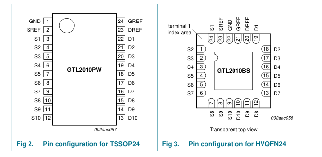
6.2 Pin description
Table 3. Pin description
| Symbol | Pin | Description | |
|---|---|---|---|
| TSSOP24 | HVQFN24 | ||
22[1]
GND
1
SREF
2
23
S1 to S10
3, 4, 5, 6, 7, 8, 9, 24, 1, 2, 3, 4, 5, 6, 10, 11, 12
7, 8, 9
D1 to D10
22, 21, 20, 19, 18, 19, 18, 17, 16, 15, 17, 16, 15, 14, 13 14, 13, 12, 11, 10
DREF
23
20
GREF
24
21
ground (0 V) source of reference transistor Port S1 to Port S10
Port D1 to Port D10
drain of reference transistor gate of reference transistor
[1] HVQFN24 package die supply ground is connected to both GND pin and exposed center pad. GND pin must be connected to supply ground for proper device operation. For enhanced thermal, electrical, and board level performance, the exposed pad needs to be soldered to the board using a corresponding thermal pad on the board and for proper heat conduction through the board, thermal vias need to be incorporated in the printed-circuit board in the thermal pad region.
3 of 20
Page 4
7. Functional description
Refer also to Figure 1 “Functional diagram”.
7.1 Function selection
Table 4. Function selection, HIGH-to-LOW translation Assumes Dn is at the higher voltage level. H = HIGH voltage level; L = LOW voltage level; X = Don’t care
GREF[1]
SREF[2]
DREF
Input Dn
Output Sn
Transistor
H
H
0 V
X
X
off
VT[3]
H
on
H
H
VT
L[4]
L
on
H
H
VT
X
X
off
L
L
0 V − VT
[1] GREF should be at least 1.5 V higher than SREF for best translator operation. [2] VT is equal to the SREF voltage. [3] Sn is not pulled up or pulled down. [4] Sn follows the Dn input LOW.
Table 5. Function selection, LOW-to-HIGH translation Assumes Dn is at the higher voltage level. H = HIGH voltage level; L = LOW voltage level; X = Don’t care
GREF[1]
SREF[2]
DREF
Input Sn
Output Dn
Transistor
H
H
0 V
X
X
off
H[3]
VT
nearly off
H
H
VT
L[4]
L
on
H
H
VT
X
X
off
L
L
0 V − VT
[1] GREF should be at least 1.5 V higher than SREF for best translator operation. [2] VT is equal to the SREF voltage. [3] Dn is pulled up to VCC through an external resistor. [4] Dn follows the Sn input LOW.
4 of 20
Page 5
8. Application design-in information
8.1 Bidirectional translation
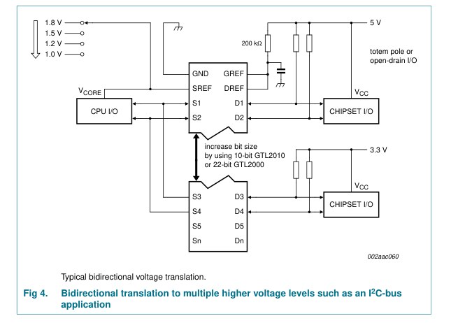
For the bidirectional clamping configuration, higher voltage to lower voltage or lower voltage to higher voltage, the GREF input must be connected to DREF and both pins pulled to HIGH side VCC through a pull-up resistor (typically 200 kΩ). A filter capacitor on DREF is recommended. The processor output can be totem pole or open-drain (pull-up resistors may be required) and the chip set output can be totem pole or open-drain (pull-up resistors are required to pull the Dn outputs to VCC). However, if either output is totem pole, data must be unidirectional or the outputs must be 3-stateable and the outputs must be controlled by some direction control mechanism to prevent HIGH-to-LOW
contentions in either direction. If both outputs are open-drain, no direction control is needed. The opposite side of the reference transistor (SREF) is connected to the processor core power supply voltage. When DREF is connected through a 200 kΩ resistor to a 3.3 V to 5.5 V VCC supply and SREF is set between 1.0 V to (VCC − 1.5 V), the output of each Sn has a maximum output voltage equal to SREF and the output of each Dn has a maximum output voltage equal to VCC.
5 of 20
Page 6
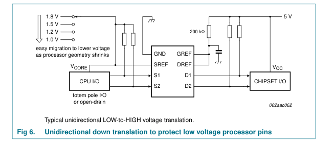
8.2 Unidirectional down translation
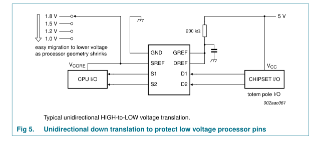
For unidirectional clamping, higher voltage to lower voltage, the GREF input must be connected to DREF and both pins pulled to the higher side VCC through a pull-up resistor (typically 200 kΩ). A filter capacitor on DREF is recommended. Pull-up resistors are required if the chip set I/Os are open-drain. The opposite side of the reference transistor (SREF) is connected to the processor core supply voltage. When DREF is connected through a 200 kΩ resistor to a 3.3 V to 5.5 V VCC supply and SREF is set between 1.0 V to (VCC − 1.5 V), the output of each Sn has a maximum output voltage equal to SREF.
8.3 Unidirectional up translation
For unidirectional up translation, lower voltage to higher voltage, the reference transistor is connected the same as for a down translation. A pull-up resistor is required on the higher voltage side (Dn or Sn) to get the full HIGH level, since the GTL-TVC device will only pass the reference source (SREF) voltage as a HIGH when doing an up translation. The driver on the lower voltage side only needs pull-up resistors if it is open-drain.
6 of 20
Page 7
8.4 Sizing pull-up resistor
The pull-up resistor value needs to limit the current through the pass transistor when it is in the ‘on’ state to about 15 mA. This will guarantee a pass voltage of 260 mV to 350 mV. If the current through the pass transistor is higher than 15 mA, the pass voltage will also be higher in the ‘on’ state. To set the current through each pass transistor at 15 mA, the pull-up resistor value is calculated as shown in Equation 1:
pull-up voltage V
– 0.35 V ( )
( ) -------------------------------------------------------------------------------
(1)
=
resistor value Ω
0.015 A
Table 6 summarizes resistor values for various reference voltages and currents at 15 mA and also at 10 mA and 3 mA. The resistor value shown in the + 10 % column or a larger value should be used to ensure that the pass voltage of the transistor would be 350 mV or less. The external driver must be able to sink the total current from the resistors on both sides of the GTL-TVC device at 0.175 V, although the 15 mA only applies to current flowing through the GTL-TVC device. See application note AN10145, “Bi-directional low voltage translators” for more information.
Table 6. Pull-up resistor values
| Voltage | Pull-up resistor value (Ω)[1] | |||||
| 15 mA[2] | 10 mA[2] | 3 mA[2] | ||||
| Nominal | + 10 %[3] | Nominal | + 10 %[3] | Nominal | + 10 %[3] | |
5.0 V
310
341
465
512
1550
1705
3.3 V
197
217
295
325
983
1082
2.5 V
143
158
215
237
717
788
1.8 V
97
106
145
160
483
532
1.5 V
77
85
115
127
383
422
1.2 V
57
63
85
94
283
312
[1] Calculated for VOL = 0.35 V. [2] Assumes output driver VOL = 0.175 V at stated current. [3] + 10 % to compensate for VCC range and resistor tolerance.
7 of 20
Page 8
9. Limiting values
Table 7. Limiting values[1] In accordance with the Absolute Maximum Rating System (IEC 60134). Symbol Parameter
Conditions
Min Max Unit
[2] −0.5
voltage on pin SREF
+7.0 V
VSREF
[2] −0.5
voltage on pin DREF
+7.0 V
VDREF
[2] −0.5
voltage on pin GREF
+7.0 V
VGREF
[2] −0.5
voltage on port Sn
+7.0 V
VSn
[2] −0.5
voltage on port Dn
+7.0 V
VDn diode current on reference pins
VI < 0 V
- −50 mA
IREFK diode current Port Sn
VI < 0 V
- −50 mA
ISK diode current Port Dn
VI < 0 V
- −50 mA
IDK clamp current per channel
channel in
- ±128 mA
IMAX
ON-state
storage temperature
−65 +150 °C
Tstg
[1] The performance capability of a high-performance integrated circuit in conjunction with its thermal environment can create junction temperatures which are detrimental to reliability. The maximum junction temperature of this integrated circuit should not exceed 150 °C. [2] The input and output negative voltage ratings may be exceeded if the input and output clamp current ratings are observed.
10. Recommended operating conditions
Table 8. Recommended operating conditions Symbol Parameter voltage on an input/output pin Sn, Dn VI/O voltage on pin SREF VSREF voltage on pin DREF VDREF voltage on pin GREF VGREF pass transistor current IPASS ambient temperature Tamb
Conditions
Min Typ Max Unit 0 - 5.5 V
[1] 0 - 5.5 V
0 - 5.5 V
0 - 5.5 V
- - 64 mA
operating in free air
−40 -
+85 °C
[1] VSREF ≤ VDREF − 1.5 V for best results in level shifting applications.
8 of 20
Page 9
11. Static characteristics
Table 9. Static characteristics Tamb = −40 °C to +85 °C, unless otherwise specified.
Typ[1] Max
Symbol
Parameter
Conditions
Min
Unit
LOW-level output voltage
VCC = 3.0 V; VSREF = 1.365 V;
- 260 350 mV
VOL
VSn or VDn = 0.175 V; Iclamp = 15.2 mA
input clamping voltage
II = −18 mA; VGREF = 0 V
- - −1.2 V
VIK
gate input leakage current
VI = 5 V; VGREF = 0 V
- - 5 µA
ILI(G)
input capacitance at gate
VI = 3 V or 0 V
- 56 - pF
Cig
off-state input/output
VO = 3 V or 0 V; VGREF = 0 V
- 7.4 - pF
Cio(off)
capacitance on-state input/output
VO = 3 V or 0 V; VGREF = 3 V
- 18.6 - pF
Cio(on)
capacitance
[2]
ON-state resistance
VI = 0 V; IO = 64 mA
Ron
VGREF = 4.5 V
- 3.5 5 Ω
VGREF = 3 V
- 4.4 7 Ω
VGREF = 2.3 V
- 5.5 9 Ω
VGREF = 1.5 V
- 67 115 Ω
[2] -
VI = 0 V; IO = 30 mA; VGREF = 1.5 V
9 15 Ω
[2] -
VI = 2.4 V; IO = 15 mA; VGREF = 4.5 V
7 10 Ω
[2] -
VI = 2.4 V; IO = 15 mA; VGREF = 3 V
58 80 Ω
[2] -
VI = 1.7 V; IO = 15 mA; VGREF = 2.3 V
50 70 Ω
[1] All typical values are measured at Tamb = 25 °C. [2] Measured by the voltage drop between the Sn and the Dn terminals at the indicated current through the switch. ON-state resistance is determined by the lowest voltage of the two (Sn or Dn) terminals.
9 of 20
Page 10
12. Dynamic characteristics
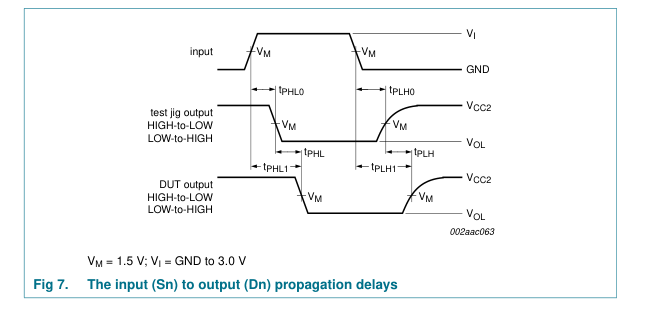
12.1 Dynamic characteristics for translator-type application
Table 10. Dynamic characteristics Tamb = −40 °C to +85 °C; Vref = 1.365 V to 1.635 V; VCC1 = 3.0 V to 3.6 V; VCC2 = 2.36 V to 2.64 V; GND = 0 V; tr = tf ≤ 3.0 ns; unless otherwise specified. Refer to Figure 9.
Typ[1]
Symbol Parameter
Conditions
Min
Max Unit
[2][3] 0.5
LOW-to-HIGH propagation delay
Sn to Dn; Dn to Sn
1.5 5.5 ns
tPLH
[2][3] 0.5
HIGH-to-LOW propagation delay
Sn to Dn; Dn to Sn
1.5 5.5 ns
tPHL
[1] All typical values are measured at VCC1 = 3.3 V, VCC2 = 2.5 V, Vref = 1.5 V and Tamb = 25 °C. [2] Propagation delay guaranteed by characterization. [3] Cio(on)(max) of 30 pF and Cio(off)(max) of 15 pF is guaranteed by design.
10 of 20
Page 11
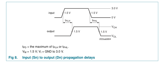
12.2 Dynamic characteristics for CBT-type application
Table 11. Dynamic characteristics Tamb = −40 °C to +85 °C; VGREF = 5 V ± 0.5 V; GND = 0 V; CL = 50 pF; unless otherwise specified. Refer to Figure 10. Symbol Parameter
Conditions
Min Typ Max Unit
[1] -
propagation delay
- 250 ps
tPD
[1] This parameter is warranted but not production tested. The propagation delay is based on the RC time constant of the typical ON-state resistance of the switch and a load capacitance of 50 pF, when driven by an ideal voltage source (zero output impedance).
11 of 20
Page 12
13. Test information
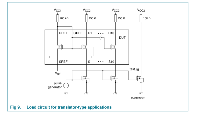
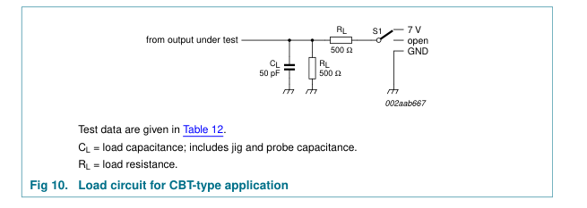
Table 12. Test data
| Test | Load | Switch | |
| C L | R L | ||
tPD
50 pF
500 Ω
open
tPLZ, tPZL
50 pF
500 Ω
7 V
tPHZ, tPZH
50 pF
500 Ω
open
12 of 20
Page 13
14. Package outline
TSSOP24: plastic thin shrink small outline package; 24 leads; body width 4.4 mm
SOT355-1
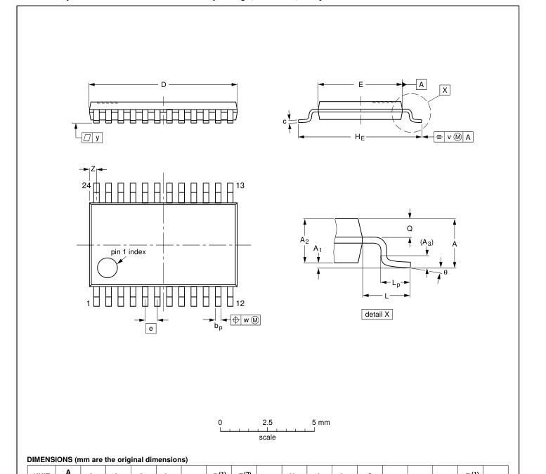

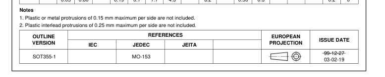
Fig 11. Package outline SOT355-1 (TSSOP24)
13 of 20
Page 14
HVQFN24: plastic thermal enhanced very thin quad flat package; no leads;
SOT616-1
24 terminals; body 4 x 4 x 0.85 mm
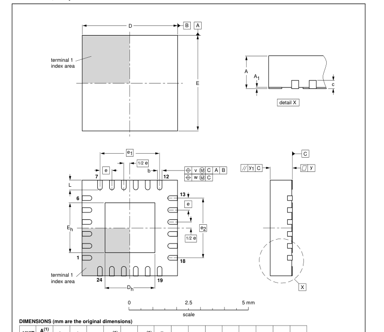

Note 1. Plastic or metal protrusions of 0.075 mm maximum per side are not included.
| OUTLINE VERSION | REFERENCES | EUROPEAN PROJECTION | ISSUE DATE | ||||
| IEC | JEDEC | JEITA | |||||
| SOT616-1 | - - - | MO-220 | - - - | 01-08-08 02-10-22 | |||
Fig 12. Package outline SOT616-1 (HVQFN24)
14 of 20
Page 15
15. Soldering of SMD packages
This text provides a very brief insight into a complex technology. A more in-depth account of soldering ICs can be found in Application Note AN10365 “Surface mount reflow soldering description”.
15.1 Introduction to soldering
Soldering is one of the most common methods through which packages are attached to Printed Circuit Boards (PCBs), to form electrical circuits. The soldered joint provides both the mechanical and the electrical connection. There is no single soldering method that is ideal for all IC packages. Wave soldering is often preferred when through-hole and Surface Mount Devices (SMDs) are mixed on one printed wiring board; however, it is not suitable for fine pitch SMDs. Reflow soldering is ideal for the small pitches and high densities that come with increased miniaturization.
15.2 Wave and reflow soldering
Wave soldering is a joining technology in which the joints are made by solder coming from a standing wave of liquid solder. The wave soldering process is suitable for the following:
- Through-hole components
- Leaded or leadless SMDs, which are glued to the surface of the printed circuit board
Not all SMDs can be wave soldered. Packages with solder balls, and some leadless packages which have solder lands underneath the body, cannot be wave soldered. Also, leaded SMDs with leads having a pitch smaller than ~0.6 mm cannot be wave soldered, due to an increased probability of bridging.
The reflow soldering process involves applying solder paste to a board, followed by component placement and exposure to a temperature profile. Leaded packages, packages with solder balls, and leadless packages are all reflow solderable.
Key characteristics in both wave and reflow soldering are:
- Board specifications, including the board finish, solder masks and vias
- Package footprints, including solder thieves and orientation
- The moisture sensitivity level of the packages
- Package placement
- Inspection and repair
- Lead-free soldering versus SnPb soldering
15.3 Wave soldering
Key characteristics in wave soldering are:
- Process issues, such as application of adhesive and flux, clinching of leads, board transport, the solder wave parameters, and the time during which components are exposed to the wave
- Solder bath specifications, including temperature and impurities
15 of 20
Page 16
15.4 Reflow soldering
Key characteristics in reflow soldering are:
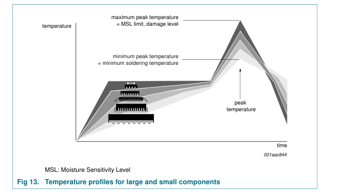
- Lead-free versus SnPb soldering; note that a lead-free reflow process usually leads to higher minimum peak temperatures (see Figure 13) than a SnPb process, thus reducing the process window
- Solder paste printing issues including smearing, release, and adjusting the process window for a mix of large and small components on one board
- Reflow temperature profile; this profile includes preheat, reflow (in which the board is heated to the peak temperature) and cooling down. It is imperative that the peak temperature is high enough for the solder to make reliable solder joints (a solder paste characteristic). In addition, the peak temperature must be low enough that the packages and/or boards are not damaged. The peak temperature of the package depends on package thickness and volume and is classified in accordance with Table 13 and 14
Table 13. SnPb eutectic process (from J-STD-020C)
| Package thickness (mm) | Package reflow temperature (°C) | |
| Volume (mm3) | ||
| < 350 | ≥ 350 | |
< 2.5
235
220
≥ 2.5
220
220
Table 14. Lead-free process (from J-STD-020C)
| Package thickness (mm) | Package reflow temperature (°C) | ||
| Volume (mm3) | |||
| < 350 | 350 to 2000 | > 2000 | |
< 1.6
260
260
260
1.6 to 2.5
260
250
245
2.5
250
245
245
Moisture sensitivity precautions, as indicated on the packing, must be respected at all times.
Studies have shown that small packages reach higher temperatures during reflow soldering, see Figure 13.
16 of 20
Page 17
For further information on temperature profiles, refer to Application Note AN10365 “Surface mount reflow soldering description”.
16. Abbreviations
Table 15. Abbreviations Acronym
Description
CDM
Charged Device Model Complementary Metal Oxide Semiconductor
CMOS DUT
Device Under Test
ESD
ElectroStatic Discharge Gunning Transceiver Logic
GTL HBM
Human Body Model
I2C-bus
Inter IC bus Low Voltage Transistor-Transistor Logic
LVTTL MM
Machine Model Negative-channel Metal Oxide Semiconductor
NMOS
Transistor-Transistor Logic
TTL
Transceiver Voltage Clamps
TVC
17 of 20
Page 18
17. Revision history
Table 16. Revision history Document ID
Release date
Data sheet status
Change notice
Supersedes
20080303
-
GTL2010_5
- The format of this data sheet has been redesigned to comply with the new identity guidelines of
Modifications:
NXP Semiconductors.
- Legal texts have been adapted to the new company name where appropriate.
- Table 7 “Limiting values[1]”: deleted (old) table note [1] (statement is now in Section 18.3 “Disclaimers”)
- Table 9 “Static characteristics”: – Ron maximum value for condition VI = 0 V; IO = 64 mA; VGREF = 1.5 V changed from 105 Ω to 115 Ω
– Symbol “IIH, gate input leakage” changed to “ILI(G), gate input leakage current”
GTL2010_5
20040728
(9397 750 13854) GTL2010_4
20030502
Product data
(9397 750 11458) GTL2010_3
20030401
Product data
(9397 750 11352) GTL2010_2
20000830
Product specification
(9397 750 07462) GTL2010_1
19990405
Product specification
-
GTL2010_4
853-2153 29981 of GTL2010_3 2003 May 01 853-2153 29603 of GTL2010_2 2003 Feb 28 853-2153 24452 of GTL2010_1 2000 Aug 30 -
-
18 of 20
Page 19
18. Legal information
18.1 Data sheet status
Document status[1][2]
Product status[3]
Definition This document contains data from the objective specification for product development.
Objective [short] data sheet
Development
This document contains data from the preliminary specification.
Preliminary [short] data sheet Qualification
This document contains the product specification.
Product [short] data sheet
Production
[1] Please consult the most recently issued document before initiating or completing a design. [2] The term ‘short data sheet’ is explained in section “Definitions”. [3] The product status of device(s) described in this document may have changed since this document was published and may differ in case of multiple devices. The latest product status information is available on the Internet at URL http://www.nxp.com.
18.2 Definitions
Draft — The document is a draft version only. The content is still under internal review and subject to formal approval, which may result in modifications or additions. NXP Semiconductors does not give any representations or warranties as to the accuracy or completeness of information included herein and shall have no liability for the consequences of use of such information. Short data sheet — A short data sheet is an extract from a full data sheet with the same product type number(s) and title. A short data sheet is intended for quick reference only and should not be relied upon to contain detailed and full information. For detailed and full information see the relevant full data
sheet, which is available on request via the local NXP Semiconductors sales office. In case of any inconsistency or conflict with the short data sheet, the full data sheet shall prevail.
18.3 Disclaimers
General — Information in this document is believed to be accurate and reliable. However, NXP Semiconductors does not give any representations or warranties, expressed or implied, as to the accuracy or completeness of such information and shall have no liability for the consequences of use of such information. Right to make changes — NXP Semiconductors reserves the right to make changes to information published in this document, including without limitation specifications and product descriptions, at any time and without notice. This document supersedes and replaces all information supplied prior to the publication hereof. Suitability for use — NXP Semiconductors products are not designed,
authorized or warranted to be suitable for use in medical, military, aircraft, space or life support equipment, nor in applications where failure or
19. Contact information
For more information, please visit: http://www.nxp.com
malfunction of an NXP Semiconductors product can reasonably be expected to result in personal injury, death or severe property or environmental damage. NXP Semiconductors accepts no liability for inclusion and/or use of NXP Semiconductors products in such equipment or applications and therefore such inclusion and/or use is at the customer’s own risk. Applications — Applications that are described herein for any of these products are for illustrative purposes only. NXP Semiconductors makes no representation or warranty that such applications will be suitable for the specified use without further testing or modification. Limiting values — Stress above one or more limiting values (as defined in
the Absolute Maximum Ratings System of IEC 60134) may cause permanent damage to the device. Limiting values are stress ratings only and operation of the device at these or any other conditions above those given in the Characteristics sections of this document is not implied. Exposure to limiting values for extended periods may affect device reliability. Terms and conditions of sale — NXP Semiconductors products are sold subject to the general terms and conditions of commercial sale, as published at http://www.nxp.com/profile/terms, including those pertaining to warranty, intellectual property rights infringement and limitation of liability, unless explicitly otherwise agreed to in writing by NXP Semiconductors. In case of
any inconsistency or conflict between information in this document and such terms and conditions, the latter will prevail. No offer to sell or license — Nothing in this document may be interpreted or construed as an offer to sell products that is open for acceptance or the grant, conveyance or implication of any license under any copyrights, patents or other industrial or intellectual property rights.
18.4 Trademarks
Notice: All referenced brands, product names, service names and trademarks are the property of their respective owners.
For sales office addresses, please send an email to: salesaddresses@nxp.com
19 of 20
Page 20
20. Contents
1 General description . . . . . . . . . . . . . . . . . . . . . . 1 2 Features . . . . . . . . . . . . . . . . . . . . . . . . . . . . . . . 1 3 Applications . . . . . . . . . . . . . . . . . . . . . . . . . . . . 2 4 Ordering information . . . . . . . . . . . . . . . . . . . . . 2 4.1 Ordering options . . . . . . . . . . . . . . . . . . . . . . . . 2 5 Functional diagram . . . . . . . . . . . . . . . . . . . . . . 2 6 Pinning information. . . . . . . . . . . . . . . . . . . . . . 3 6.1 Pinning . . . . . . . . . . . . . . . . . . . . . . . . . . . . . . . 3 6.2 Pin description . . . . . . . . . . . . . . . . . . . . . . . . . 3 7 Functional description . . . . . . . . . . . . . . . . . . . 4
7.1 Function selection. . . . . . . . . . . . . . . . . . . . . . . 4 8 Application design-in information . . . . . . . . . . 5 8.1 Bidirectional translation. . . . . . . . . . . . . . . . . . . 5 8.2 Unidirectional down translation. . . . . . . . . . . . . 6 8.3 Unidirectional up translation . . . . . . . . . . . . . . . 6 8.4 Sizing pull-up resistor . . . . . . . . . . . . . . . . . . . . 7 9 Limiting values. . . . . . . . . . . . . . . . . . . . . . . . . . 8 10 Recommended operating conditions. . . . . . . . 8 11 Static characteristics. . . . . . . . . . . . . . . . . . . . . 9 12 Dynamic characteristics . . . . . . . . . . . . . . . . . 10 12.1 Dynamic characteristics for translator-type
application. . . . . . . . . . . . . . . . . . . . . . . . . . . . 10 12.2 Dynamic characteristics for CBT-type application. . . . . . . . . . . . . . . . . . . . . . . . . . . . 11 13 Test information. . . . . . . . . . . . . . . . . . . . . . . . 12 14 Package outline . . . . . . . . . . . . . . . . . . . . . . . . 13 15 Soldering of SMD packages . . . . . . . . . . . . . . 15 15.1 Introduction to soldering . . . . . . . . . . . . . . . . . 15 15.2 Wave and reflow soldering . . . . . . . . . . . . . . . 15 15.3 Wave soldering . . . . . . . . . . . . . . . . . . . . . . . . 15 15.4 Reflow soldering . . . . . . . . . . . . . . . . . . . . . . . 16 16 Abbreviations. . . . . . . . . . . . . . . . . . . . . . . . . . 17
17 Revision history. . . . . . . . . . . . . . . . . . . . . . . . 18 18 Legal information. . . . . . . . . . . . . . . . . . . . . . . 19 18.1 Data sheet status . . . . . . . . . . . . . . . . . . . . . . 19 18.2 Definitions. . . . . . . . . . . . . . . . . . . . . . . . . . . . 19 18.3 Disclaimers . . . . . . . . . . . . . . . . . . . . . . . . . . . 19 18.4 Trademarks. . . . . . . . . . . . . . . . . . . . . . . . . . . 19 19 Contact information. . . . . . . . . . . . . . . . . . . . . 19 20 Contents . . . . . . . . . . . . . . . . . . . . . . . . . . . . . . 20

Please be aware that important notices concerning this document and the product(s) described herein, have been included in section ‘Legal information’.
© NXP B.V. 2008.
All rights reserved.
For more information, please visit: http://www.nxp.com For sales office addresses, please send an email to: salesaddresses@nxp.com
Date of release: 3 March 2008 Document identifier: GTL2010_6